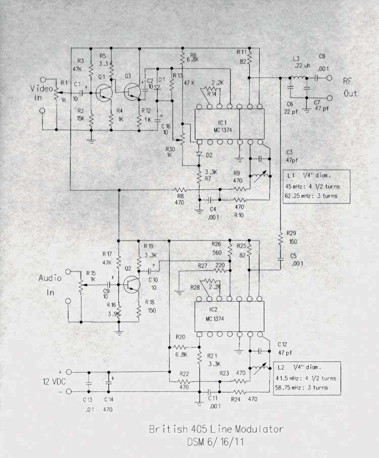
Early Television 405 Line ModulatorAlso available from the museum General: This is a modulator primarily for the old 405 line British TV standard. It will work on Band 1 channels (45 mHz video, 41.5 mHz audio to 62.25 mHz video, 58.75 mHz audio or any frequency in between). It is not crystal controlled, but is quite stable. Visual carrier output is about +15 dBmv. Aural carrier output is about 6 db lower. It requires an external 9-12 v DC power supply. It can be modified to work with prewar American sets. Circuit Description: Q1 is an inverter for the video signal. Q2 is an emitter follower. D1 clamps the sync tip to a reference voltage to keep it at zero RF. IC1 is a MC1374 oscillator/modulator IC for the visual channel. Frequency is determined by C3 and L1. Q3 amplifies the audio input. IC2 is the oscillator/modulator for the aural channel. Frequency is determined by C12 and L2. Be sure to use temperature stable capacitors for C3 and C12. L1 and L2 are built on 1/4 inch coil forms with adjustable powdered iron cores. Q1, Q2 and Q3 are general purpose NPN amplifier or switching transistors. D1 and D2 are silicon switching diodes such as 1N914. Housing: I use a 3 x 5 x 2 inch aluminum housing from Radio Shack. On the front I put the video and audio level controls and a power switch. On the rear I put RCA jacks for video and audio input, and an F fitting for RF output. I drill holes in the top to allow tuning of the aural and visual frequencies. Adjustment: Temporarily remove R 29. Connect a 1 v pp video signal to the input. Connect a frequency counter or spectrum analyzer to C5. Adjust L2 for the proper sound carrier frequency. Connect the frequency counter or spectrum analyzer to the RF output. Adjust L1 for the proper video carrier frequency. Replace R29. R30 should be adjusted to produce zero RF level at the sync tips. Connect a wideband scope to the RF output. Temporarily remove R29. Turn R1 up until the video starts to compress, then back it off slightly. Adjust R30 so that the sync tips produce as close to zero RF output as possible. If no wideband scope is available, a narrow band scope can be used with a detector, or the scope can be connected to the video output of a working 405 line set. If no scope is available, set R30 at the point that results in the best sync stability while watching a working TV receiver. If neither of these test instruments is available, use a working 405 line set to adjust sound and video frequencies (with R29 installed)< Modifications: To change the level of the aural carrier, R29 can be varied. Some external power supplies have somewhat poor AC smoothing, which can result in hum in the video. Inserting a 50 ohm 1/2 watt resistor in series with the plus lead of the power supply will cure the problem. American Prewar Sets: The modulator can be modified to provide signals for early electronic American sets (AM sound) with the following changes. The revised schematic is labeled"American Prewar Modification". Refer to the PC board layout sheet. Do not install R4, R5, Q1, R30, C16 or D2. Install a jumper between where the base and collector of Q1 would have gone on the PC board. Install a jumper where D2 would have gone. Install R4A where C16 would have gone. Install D1 with the band end to the left (reversed from what is shown on the layout sheet). Install one end of R5A in the lower hole marked for R5. Install the other end where the wiper of R30 would have gone. Information: The kit consists of the PC board, two MC1374 ICs and two ceramic coil forms. Ordering Instructions: The price is $40, including U.S. or international shipping. You can mail a check to us at the Early Television Museum, 5396 Franklin Street, Hilliard, Ohio, or order online:
For more information email us at info@earlytelevision.org
|