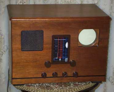
Early Electronic Television HMV 904 ReplicaThe following is by Victor Barker, who has built this very nice replica of a prewar HMV 904:
It was 1958 when I was a teenager and living with my parents near London that I was given an HMV 904 T.V. to experiment with. I managed to get it working by repairing the vertical timebase and replacing a couple of valves, the mixer and the sync limiter. Unfortunately my father was conned into selling it to a associate of his, much to my displeasure. In those days it was the parents who were in charge. I was at the time apprenticed to an electronic instrument manufacturer making R.F. test gear for the BBC amongst others for T.V. transmitting stations and receiver manufacturers. I was very interested in the technique of television engineering and the bug is still with me.
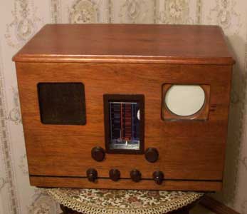
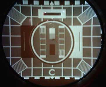
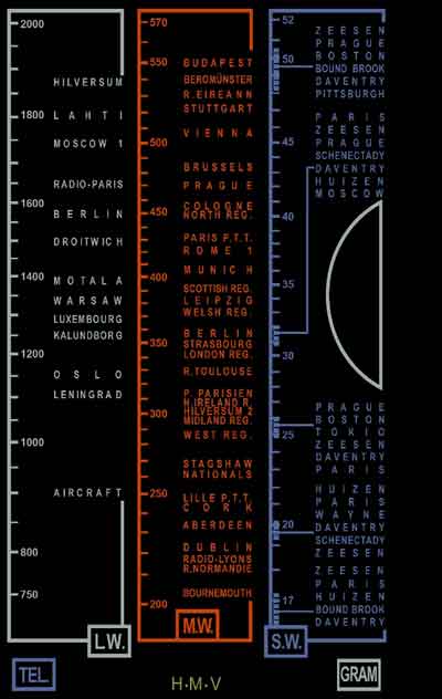
The original CRT was a major stumbling block because of the near if not total impossibility of obtaining one, various 5 inch tubes were tried but only two types were in any way acceptable. The tubes were both of American origin being the 5AXP4 a non aluminised electrostatic test tube and a 5FP4 a magnetic focused white screen tube very similar to the very common 5FP7 but designed for TV camera viewfinder use. The latter tube was the type finally used, it performs flawlessly and even at the very low E.H.T. of 2.5 KV employed in the 904 design is not the limiting factor determining the picture resolution. The brightness is adequate under subdued lighting as with the original set using an EMISCOPE 3/1. At the time of construction access to any coil winding information was not available and still isn't I used valve data, circuit fixed capacitances and guestimates to determine the total circuit capacitances in order to design the R.F. and I.F. coils. Some degree of empiric determination was used in a few areas. Aluminium tuning cores were used where variable permeability was required. The tuning scale mechanism employing an epicyclic drive was engineered to the same spec as the original set, the logging dial is somewhat simpler at present but designed to be modifiable if I can find suitable parts to replicate the original chain drive. The dial was made from a photograph of an original dial that was re- drawn using cad program on a P.C. and finally printed onto photographic paper and used as a rear dial plate rather than printing onto the rear of the glass frontplate.
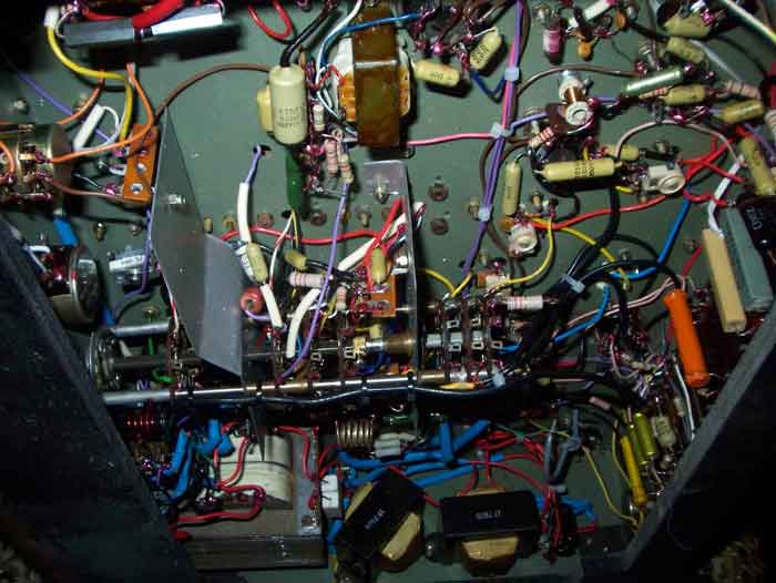
Most
of the wiring unfortunately is carried out using plastic
covered wire, whilst many of the short interconnects are
wired with 22 s.w.g. t.c.w. and sleeved with mil grade black
cotton impregnated sleeving removed from wartime radar
equipment of British design. The tagboards are of wartime
vintage and also British, they are almost identical to the
ones used in the original 904, they appear to be made by the
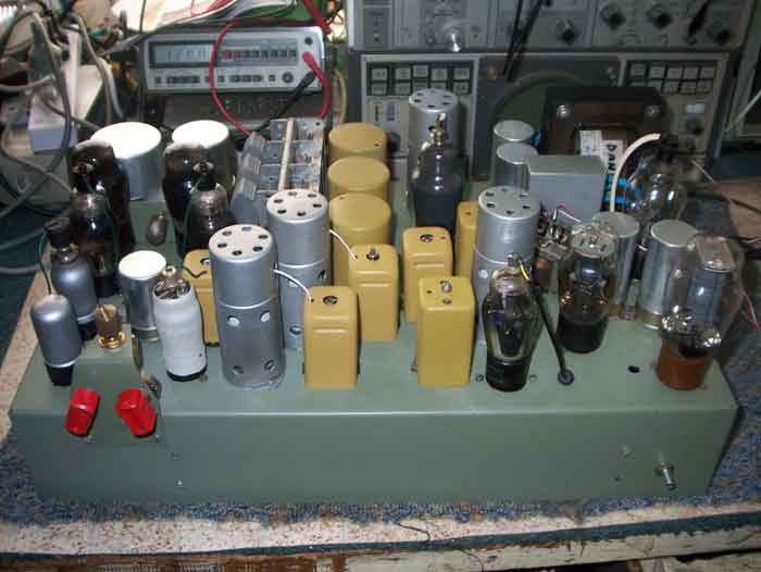
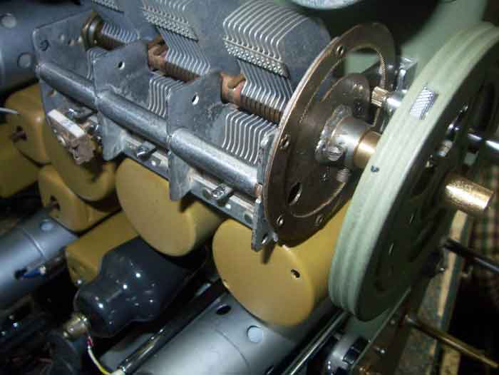
same company. How lucky can one be? The tuning capacitor was removed from an old Australian radio but was made by the same company that made the 904 unit even the direction of rotation and the fixing holes I have subsequently discovered are the same. Different trimmers were fitted to accommodate local requirements. The multiple electro housed in a rectangular metal box was faithfully reproduced using modern electros of higher voltage rating. I
have employed different sockets for the inputs at the rear
of the chassis to match the banana plugs that were available
at the time of construction, I refer to the aerial panel.
Cotton covered mains cord is employed to enhance the
appearance but does employ an earth lead to conform to local
safety regulations, the original set did not, a separate
earth was recommended.
Circuit differences are minor and few in number, they are
essentially: the use of a vertical output transformer
because I have not been able to find suitable wire to make
the very high impedance vertical coils needed in the
deflection yoke when resistive/capacitive coupling to the
output valve is employed as in the original design. When a
suitable yoke becomes available the transformer will be
removed and the circuit retuned to the original arrangement.
The circuit is otherwise unaltered except for a change in
the output valves bias resistor. Use of silicon diodes is
employed in a voltage doubler at present for the E.H.T.
supply because the only available
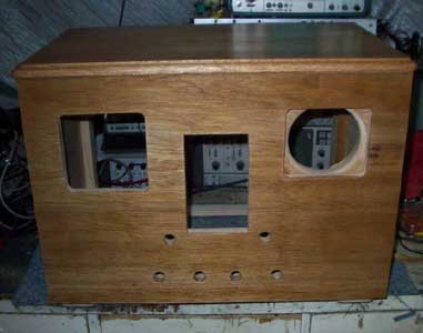
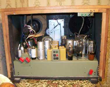
The chassis layout is a direct copy of the original and the dimensions are nearly the same, the exception being that the chassis is almost half an inch higher to accommodate one of the power transformers.
Obtaining suitable control knobs was solved by having the
volume and tuning knobs made from aluminium and machined on
a lathe whilst the other knobs were standard radio knobs
suitably drilled and modified where required for the
concentric arrangement for the contrast and brightness and
the vertical and horizontal hold controls. All knobs were
dipped in enamel paint to give them the original bakelite
appearance. The escutcheon around the radio dial is made
from thin timber as found in
A few comments about the original design may well be in order. Firstly I have every admiration for the designers of the time. The development of the circuitry during 1937 shows how well they mastered the myriad of problems they were faced with. The sync separator for one is quite a clever arrangement whereby a diode suitably biased increases the effective video detector anode load during the sync pulses thereby more than doubling the sync pulse amplitude at grid of the sync limiter. This is achieved without reducing the video bandwidth and the method employed enables the sync circuits to be isolated from the video feed to the C.R.T. cathode, again helping preserve bandwidth. The video detector is an anode bend detector and quite progressive in the television technique for its period, it re appeared after the war in a number of Philips T.V. receivers.
VB July 25. 2009 |