Early Color Television RCA CPA Prototype RestorationNow that most of the schematic has been traced, I will begin the long process of trying to get the chassis working. April 4, 2012
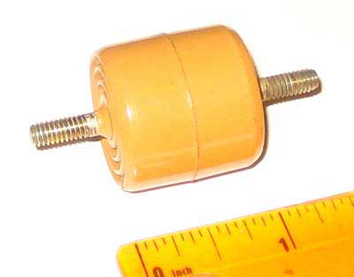
April 5, 2012 I've made some significant progress, but have a mystery. The yoke had a wire broken on it. Fixing it resulted in 17 kv of HV. I discovered the yoke problem by unplugging it. The HV didn't change. I then measured the resistance and one half was open. Removed the rivets that held the plastic cover on the rear and saw arcing at one of the terminals where the heavy wire to the plug is soldered. I removed the fine wire to the winding and re-soldered it to the terminal. Now the mystery. The doorknob capacitor on the HV line looks to me to be at most 15 kv. It is only slightly bigger than the ones used in black and white sets. I measured it and it is 500 pf, but there are no markings on it. The negative end is returned to the focus line (about 2 kv), so at most the HV of this chassis would be 17 kv. I'm not convinced that 17 kv is the design voltage. Bob Galanter has a 20 kv doorknob that is almost the same size as the one in the chassis, so I think that the chassis may be designed for 20 kv (tying the negative lead of the doorknob to the 2 kv focus voltage gives a maximum of 22 kv using a 20 kv doorknob). I may still have a fault. April 6, 2012 I now have 21 kv. My power supply has two sections: 330 v. and 410 v. I had been using the 330 v sections for the tests. I moved to the 410 v section and the HV came up. The doorknob didn't explode, so it must be a 20 kv one. It is the same exact dimensions as the one Bob Galanter has that is marked 20 kv. Connected the filament supply for the tuner/if/video sections and hooked up a signal. Got nice clean video at the output of the video amp. April 7, 2012 Today was a frustrating day with the prototype. I decided to work on the AGC and sync. April 8, 2012 Shows why it is good to put something aside when you reach an impasse. Today I discovered that the AGC and sync tubes were missing, though the tube shields were in place. I put in the AGC tube, but still nothing. Then I discovered a bad 4 mfd electrolytic I had missed. Replaced it, and then had some effect when I changed the AGC control. I attached a bias supply to the AGC line and determined that I needed about -3 volts on the line for an undistorted video waveform with the RF input I was supplying. The AGC control was in its full counterclockwise position when the AGC voltage was at its maximum negative (about -1 volt). Because I suspect that I need a power supply with about 400 volts output compared to the 330 I now have, I experimented with the values of the resistors to B+ and to ground connected to the AGC control. I discovered that if I replaced the 10k resistor to ground with a 2.2k, the AGC voltage could be adjusted to -3, and it changed with signal level changes. I decided to stop at that point and declare success until I get the proper power supply. Installing the sync tube made the sync work. I now have nice pulses at the vertical and horizontal oscillators. The horizontal oscillator locks nicely. I haven't done any work on the vertical section yet, but I have a good vertical pulse on the output of the integrator. I then used a capacitor to bridge the place where I think the delay line went (from the cathode of V9A to the grid of V9B). I have video at the output of the 3 matrix tubes. Here is what I still need to do: 1. Get the vertical section going 2. Install a delay line from a more modern set and see if it passes video without degradation or too much loss. 3. Plug a 3.58 crystal into the oscillator and see if I can get it to work. 4. Sweep the chroma amp to see its response 5. Connect the cut wires in the demodulator circuits and install the missing parts Then I'll see if I get anything like color out of the thing with a NTSC input. April 9, 2012 Got the vertical section working - bad tube plus I had knocked loose a wire while documenting it. April 11, 2012 Today I did a video IF alignment. It went well, almost like the Sams said it should. I now have an essentially flat response from 45.0 mHz to 42.25 mHz, down 3 db at 45.75 mHz. This is what the RCA black and white response is supposed to be. I didn't have time to check it through the tuner, which I'll do tomorrow. April 14, 2012 The low video was due to a bad detector diode. I replaced it and did the alignment over again in case there was a difference (there was). I now have a good curve and about 4 volts of video out of the detector. Video waveform looks good. April 15, 2012 Today is the last time I'll be able to work on the chassis for a couple of weeks. May 16, 2012 I spent some time yesterday stuffing 4 of the electrolytics. The main advantage was that it cleared up space near the reference One of the problems with working on this set is that parts have been
clipped out, so when something doesn't work I have that added May 17, 2012 Today was one step forward, two backward. I think I got the AGC working by reducing the 340 supply to about 300. However, just as I was making final measurements I banged on the chassis to clear up an intermittent problem in the tuner (I'll deal with it tomorrow), I knocked a loose nut (left over from the stuffing the electrolytics) into a position where it shorted out the 310 v line, frying the two centering pots. Amazingly, they still have continuity, but the cases have some sort of short to the wipers. For now I've just isolated them from the chassis until I can find out what is wrong. May 19, 2012 I have never worked on a set that has had so many faults. May 20, 2012 I wired the RF input properly, and now the video waveform has very little noise. AGC and sync stability at last. Everything looks good. May 21 It really feels good when things come together. AGC and sync are still stable. I found that I had accidentally disconnected C123 when fixing the solder bridge. Putting it back cured the poor IF response (don't ask me how). That left me with the clipping of the whiter areas of the waveform. This had me stumped for a while. Then I realized the obvious. I was putting too much video into the modulator. It has a 75 ohm termination switch, which was off. Turning it on cured the problem. May 23
May 24: Today I took apart the tuner, cleaned the contacts, and replaced the missing LO adjusment screw for channel 3. I took the 3.58 trap that is next to the delay line in my donor CT-100 chassis and installed it in a similar location in the prototype. It does a good job of reducing the 3.58 mHz signal in the luminance channel. Tomorrow I will make an extension cable for the 15GP22. I will use a set with a good 15G in it, install the prototype chassis yoke, and hook it up. With luck, I will be able to see some sort of color on it. May 25: Couldn't make an extension cable, so I made a mount for a 15G using a mask donated by Nick Williams and a shield salvaged from one of my Dage 15 inch monitors.
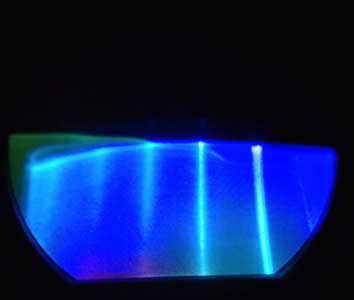
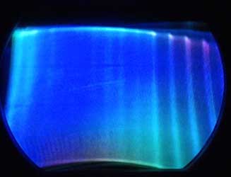
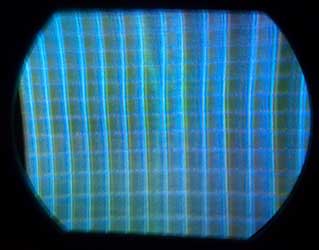
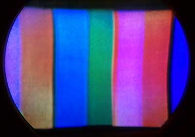
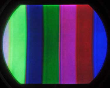
With high hopes I connected the chassis and this is what I saw:
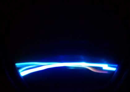
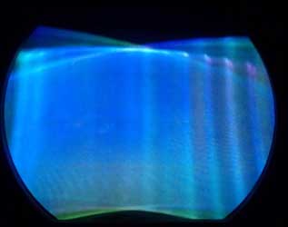
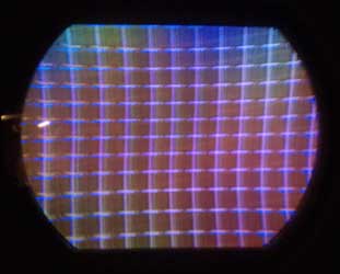
The white vertical lines are some sort of foldover in the horizontal sweep. May 26, 2012 Here is what I tried today: I when measuring the focus voltage at the CRT I noticed that it is erratic. It is stable coming out of the focus pot. I will track this down later today. Maybe there is a problem with something in the dynamic convergence circuits (though the tubes are out) that is causing the erratic focus voltage and the convergence problem?
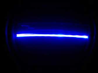
Here are screen shots of the rasters. Notice that the blue is almost normal, while the red and green tilt substantially. May 27, 2012 Success! R456 in the focus circuit went bad, which is what was causing the erratic focus voltage.
So the problems were 1) the yoke extension cable and 2) the original yoke. May 28, 2012 Today's Progress (and the last report for a couple of months).
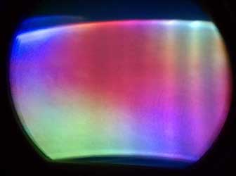
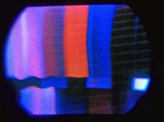
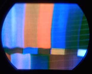
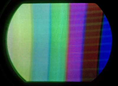
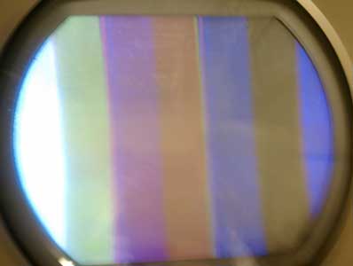
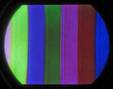
September 7, 2012 September 9, 2012 Today I messed with the R-Y and B-Y demods. After playing with all the adjustments in the 3.58 osc circuit, I finally concluded that I could either get a proper R-Y waveform, or what appeared to be an inverted B-Y waveform, but I couldn't get them simultaneously because they required different settings of the trimmers. Now, for the exciting news. By moving V20 (R-Y) to pin 4 and V21 (B-Y) to pin 3 I now have proper waveforms and a real (though poor) NTSC color pattern on the screen. The green bar is compressed because I turned the width down to get all the bars on the screen and that screwed up the linearity. September 10, 2012. I spent a few minutes with the width, background and gain adjustments, and here is what the screen looks like now:
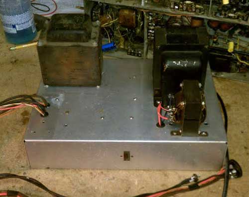
September 14, 2012. I took a break to rebuilt the power supply. I had a chassis with the 370v supply and one filament transformer, and a CT-100 transformer and voltage doubler "air wired" on the bench. I had an old aluminum chassis which I used to consolidate everything.
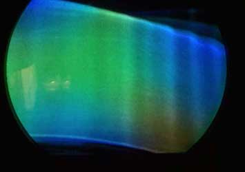
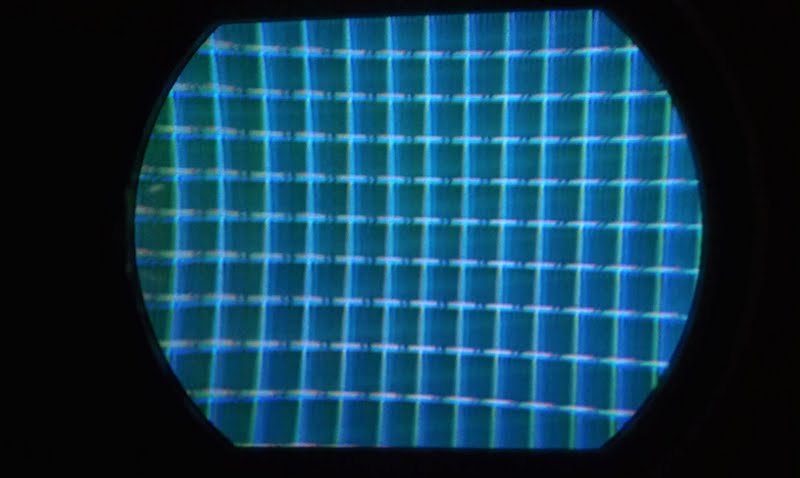
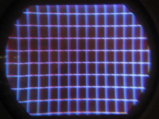
September 15, 2012 Today I worked on high voltage and focus. If you remember back to when I first got the chassis working I was only able to get about 18kv out of it. Now, for some reason, I have almost 25kv with the regulator disconnected. Maybe the flyback had moisture in it that has worked itself out? I have no other explanation. Here is a screen shot showing where I am with convergence. We have no horizontal dynamic convergence circuit, and I haven't messed with the vertical dynamic convergence.
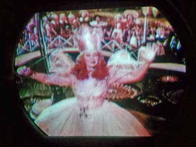
September 17, 2012 Today I worked some more on the color demods. November 4, 2012 Finally got a chance to get back to the CPA prototype. November 5, 2012 CPA at last! This afternoon I saw CPA on Nick's prototype set, the first time since 1952 that anyone had seen it. The problem was the setting of R352, the diode bias adjustment. I had to eliminate R351 to allow R352 to adjust to the right point for the diodes to switch.
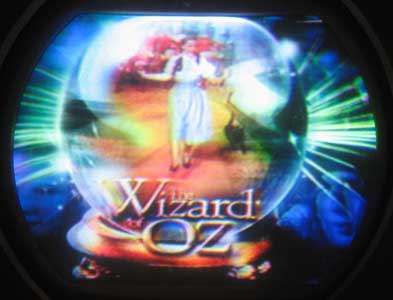
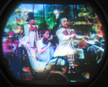
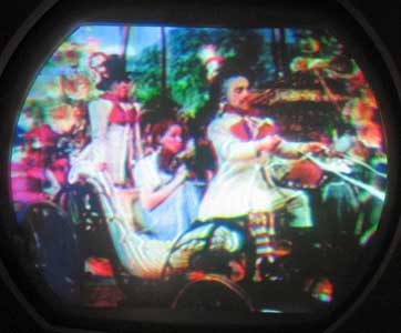
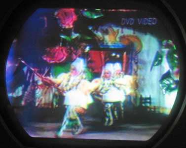
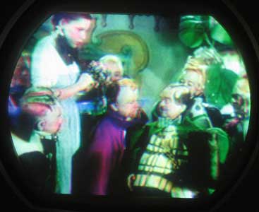
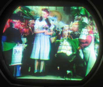
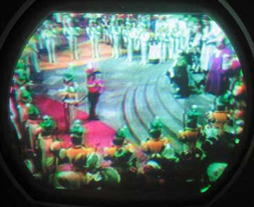
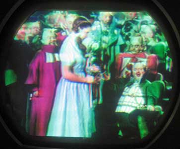
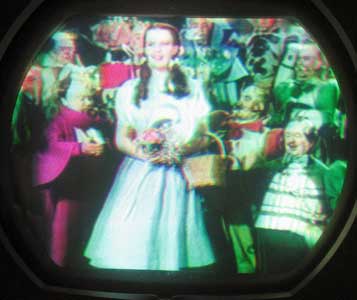
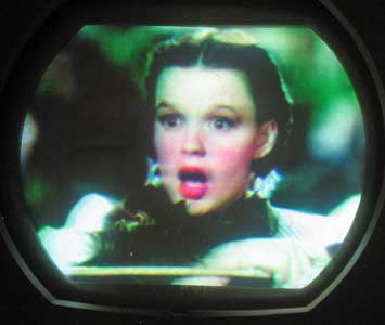
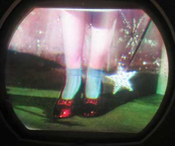
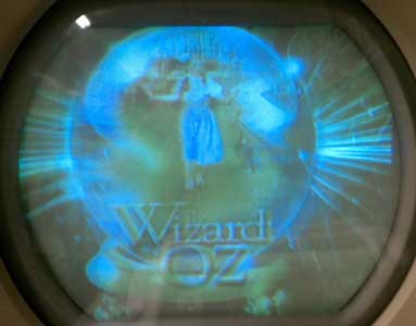
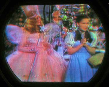
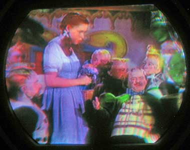
The color balance is off, so the colors aren't exactly right, but they are the same as when I turn off CPA in Darryl's converter. November 17, 2012 The Wizard of Oz on CPA:
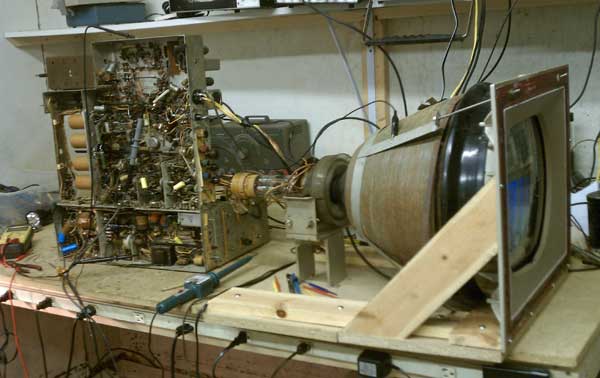
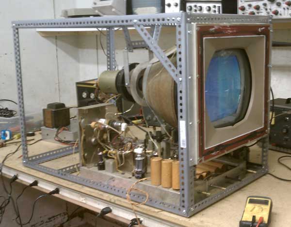
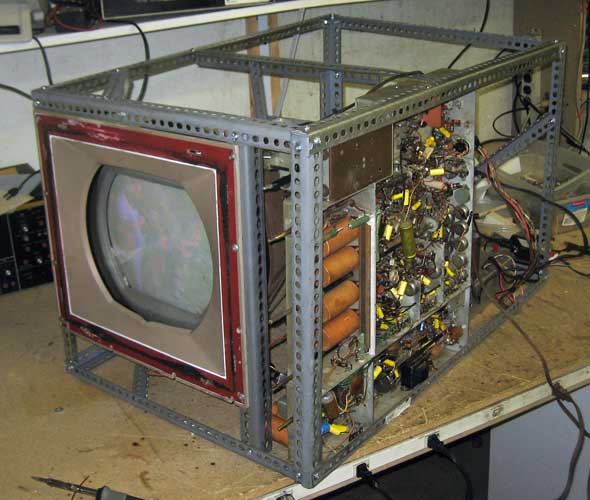
There is still much to do, especially on convergence. Though the vertical dynamic convergence circuit is there and should work, parts are missing in the horizontal circuit. We will have to experiment to find what will work. Today I plan to build a metal frame out of angle iron to hold the chassis, tube and power supply so that it will be easier to make adjustments. I will also install a better 15GP22 - the tube I'm using has a weak red gun. Then I'll start working on the convergence. There is also work to do on the focus voltage - the pot is at one extreme, either due to resistor aging or to the fact that we are using a different CRT than the original prototype. November 23, 2012 Here is the frame I made. It makes it easy to adjust stuff and keeps the CRT and yoke stable.
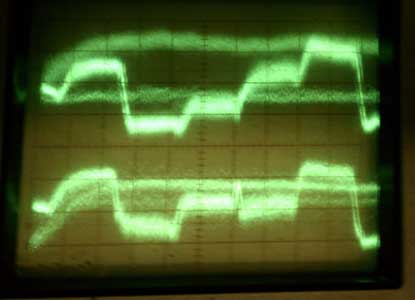
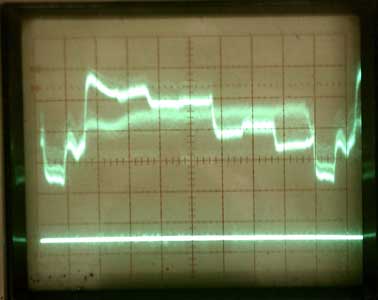
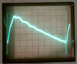
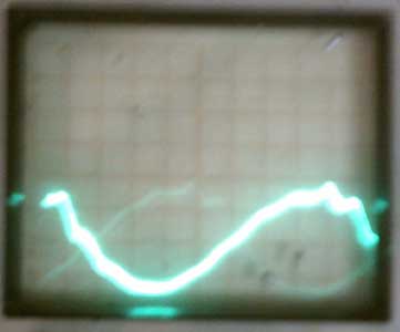
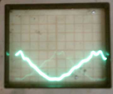
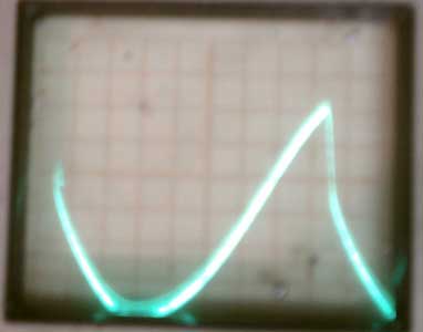
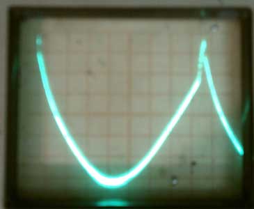
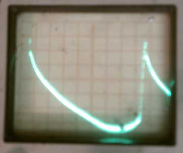
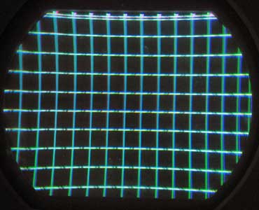
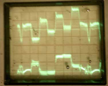
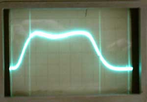
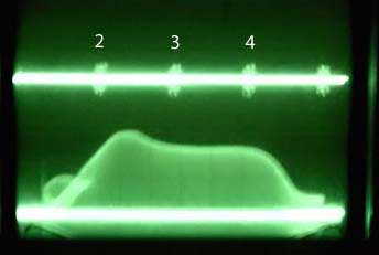
Convergence: I got the vertical dynamic circuit to work, at least the controls produce waveforms that can be adjusted. I installed the horizontal phasing coil from the CT-100 and wired the horizontal dynamic circuit like I think it was originally. I get a waveform that will change in amplitude (by adjusting the pot in the cathode of the hor. output tube), but the phasing coil doesn't change the phase. I suspect it is the wrong inductance. November 24, 2012 Worked some more on convergence. I can see that the hor. dynamic circuit will work if I get the right inductor. Vertical doesn't have a great deal of effect, so I need to see what is wrong. Even without the dynamic convergence circuits working the convergence isn't bad. November 26, 2012 I did some more exploration of the glitch in the horizontal waveform. Changing to the original yoke made no difference, and nothing else helped. I did notice that with the new 450 v supply for the hor. osc. that adjusting the hor. drive trimmer made the wavy line disappear off the side. Also, I removed the 2500 ohm resistor I'd put on the hor. out. screen grid, and the width was fine. So it appears that the horizontal section is working well,even with the waveform glitch, so I won't look further. Today I solved one of the mysteries I've been putting off tackling, quite by accident. I've been able to get a balanced waveform out of the R-Y demod. By that I mean that the two phases produce the same amplitude outputs. But when the R-Y outputs are balance, the B-Y are not. This doesn't appear visible in the picture because I believe the two levels are averaged and the rate is quick enough not to be visible. But it always bothered me. Everything appears to be stable now. November 28, 2012 I modified by metal frame to make adjustment of the yoke easier so I can get better purity. November 30, 2012 The inductors arrived from John Folsom. The 130-250 uh one works great. Attached are the horizontal dynamic convergence waveforms at minimum and maximum inductance. Though I haven't done a convergence yet I can see that it should work.
December 1, 2012 Success! After the realization I had (last email) that the parabolic signal didn't do anything, I started thinking about what could create the proper convergence waveform. What I had was a sawtooth, sloped one way. I figured that if I put a sawtooth sloped the other way on the grid of V27A I would have something with a dip in the middle. I removed the wire that went from R417 to the cathode of V26B and connected the 100k "resistor to nowhere" through a .1 to the plate of V26B, where I had a sawtooth of high amplitude of the opposite polarity.
This works so well I think it must be how it was done originally. The mystery is how the wire from the cathode of V26B to R417 got there. December 2, 2012 Here is the convergence. It is very good, and can probably be better with more care. Please ignore the color balance and purity. I'll work on that next. Also, the focus is actually very good. The problem is in the photography:
You will notice a ghost to the right of the vertical bars. This is my next challenge - I'll probably have to do another IF alignment. I have posted the latest revisions to the schematics - I've found a bunch of errors, and all the circuit changes I've done are there. The links are at the top of this page.
A portion of the screen, enlarged, to show the ghosting. There are two possible sources: IF alignment and problems in the video amplifiers. December 4, 2012 Today I discovered the source of the main ringing - a resistor and inductor at the grid of the video amplifier. Removing the inductor eliminates the ringing. I have no idea why - maybe there are parts missing there? In any case, most of the defects in the picture are now gone. There is still a minor ghost about 1/4 inch away from sharp lines. Here are pictures taken today. The photography isn't perfect, and the picture on the screen is much sharper than the photos. Also, the color balance was done very quickly, and can be much better.
December 5 I thought I'd solved the mystery of why shorting out the inductor from the grid of the video amp to ground greatly reduced the ringing. The RCA 21 inch b &w set that was the model for the IF strip in the CPA chassis also uses the same video amp. The Sams shows a 6800 ohm resistor in parallel with the inductor, which is missing in the CPA chassis. I added it, but the ringing was still pronounced (the first "ring" was over 10% of the value of the pulse). The Sams also showed a 3300 ohm resistor in parallel with the inductor from the detector diode to the video amp. I added that resistor, and replaced the short across the inductor to ground. The ringing disappeared (I can't see it with the pulse full screen on the scope). So, still a mystery, but I'm not going any further. While making these changes I compared the amplitude of the burst to make sure that they weren't attenuating high frequencies, and found that the burst stayed the same. December 7 Now that the picture is so much better flicker is visible at times. I've never been satisfied with the symmetry of the two phases coming out of the R-Y demod. This is because the switching affects the B-Y symmetry, and I had to make a compromise, resulting in neither waveform having the same shape in both phases. This contributes to the flicker. December 8 had a 33K 2 watt carbon resistor go bad by shorting (2 ohms). I've never had that happen before. Fried a choke in the power supply. I will install some fuses. Here are two photos showing the wrong phase:
December 12 At John Folsom's suggestion, I rebuilt the metal rack that holds the chassis and CRT so that the chassis is on its side. That way it doesn't get as hot underneath, I can work on it without tipping it over, and when it is put on display people can see both the top and bottom of the chassis. I worked some more with the green retrace shading bar. By accident I discovered that it goes away with a particular setting of the burst and osc. adjustments. So, I guess that is fixed.
December 14 I'm finished for now. Attached are a couple of screen shots, though the picture looks better on the screen. I didn't pay much attention to convergence when I took them. A couple more observations. I noticed that the front control shaft lengths are all different. I think that means that this chassis was never put in a cabinet. Also, the chassis isn't square. It is almost 1 inch shorter on the tuner side than on the HV cage side.
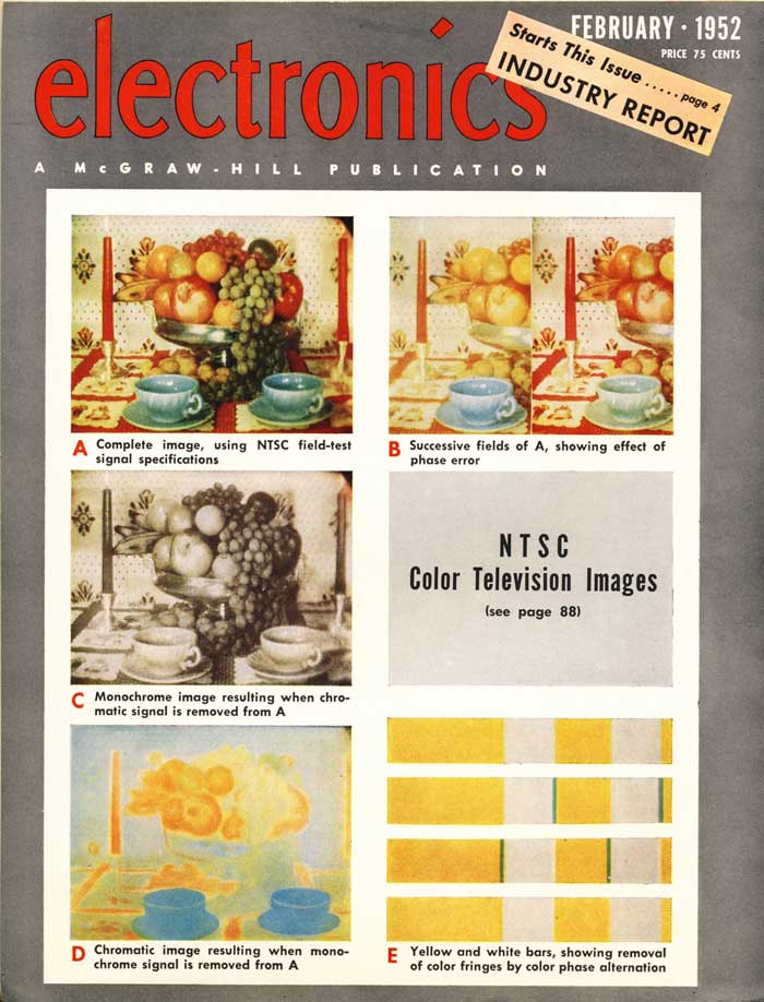
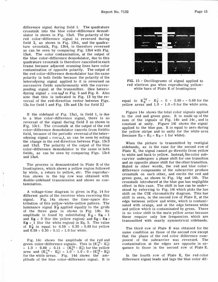
December 21, 2012 At Ed Reitan's request, I took some photos of color bars with CPA on and off to see if cancellation of phase errors could be seen between the white and yellow bars. Here is a cover and one page from an article from Electronics magazine describing this cancellation (courtesy of Ed Reitan):
I took 4 shots of each of 2 conditions, using a shutter speed of 1/15 second, and selected the best photo of each condition to post here:
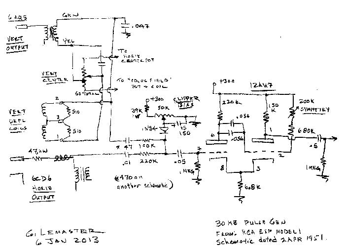
It appears that quadrature phase cancellation is taking place with CPA. January 6, 2013 George Lemaster wrote us, with information on how RCA accomplished field one detection with a single tube:
After some initial confusion about the polarity of the vertical pulse, the operation of the circuit was understood. Positive going pulses from the horizontal and vertical sweep are combined and fed to a diode clipper. At field one, the horizontal pulse coincides with the vertical, resulting in increased amplitude at the diode. At field two, the pulses don't coincide. The clipper level is set so that only the higher (field one) pulse reaches the grid of the multivibrator. Over the next couple of weeks Cliff Benham breadboarded the circuit and connected it to a RCA 630 chassis. With the help of John Folsom, he was able to get it to work and document the pulse levels that worked best with the circuit. January 19, 2013 I arrived back in Columbus for a visit and built the circuit, first on a breadboard, then on the prototype chassis. Some changes were needed to connect the circuit to the H and V signals in the prototype chassis, but it worked basically as Cliff had described. The prototype now locks automatically to the proper CPA phase. I am convinced that this circuit (or one very similar) was what was originally in the prototype chassis. The evidence is this: 1) Though there are 3 available triode sections on the chassis where the switching could have been implemented, one of these sections had never been used (nothing had been soldered to the tube socket). This means that RCA implemented the switching using a single dual triode. 2) There was a 5-50 pf trimmer capacitor on a terminal strip in the vertical sweep section. Such a trimmer could not have been used in the vertical sweep because of its low value. The trimmer does, however, work perfectly to adjust the level of the V pulse to the CPA switcher (C3435 on the Color With CPA schematic). 3) There is an emply lug on the terminal strip next to the horizontal pulse line from the flyback. This is where I obtained the H pulse for the CPA switcher. There is evidence that the lug once had components attached to it (R360 and R361 on the schematic). I believe we are to the end of the road. All of the mysteries of the CPA prototype have now been uncovered. Februay 5, 2013 My next step with the CPA chassis is to recheck the alignment.
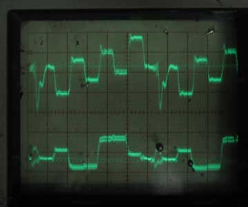
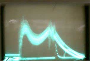
After playing with different components I decided that changing the filter would defeat the purpose of restoring this chassis. The idea is to see what CPA looked like in 1951, so I decided to keep the original filter design and simply align it for as close to 2.9 to 4.2 as I could. The best I could do was about 2.2 to 4.2. Here is the response:
Then I swept the R-Y and B-7 demodulators, which according the Ed's documentation should be flat to about 1 mHz. The R-Y demod was, in fact, flat to 1 mHz, then rolled off. The B-Y demod, however, was flat to only 500 kHz. Was this changed when the chassis was converted to NTSC, or was it originally that way? February 6, 2013 I decided to align both demodulators for 1 mHz bandpass. This is almost certainly the way it was originally - the modification to the B-Y demod may have been done when they changed the chassis to NTSC. Here is the response I got on both demods (the marker is 1 mHz):
I also cleaned up some loose ends. The vertical centering control was falling apart, and would arc to the chassis occasionally. I replaced it. Also, during the alignment process smoke started coming from the isolation transformer in the filament of the damper. One of the two micas from the filament to ground shorted. I replaced all three in that circuit. I am ready to move the chassis onto the museum floor and do a complete adjustment - purity, convergence, black and white balance, and color balance. |
|||||||||||||||||||||||||||||||||||||||||||||

