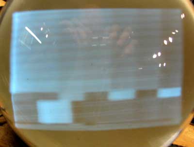
Postwar Television Telekit Model 7 RestorationThis set was found in a closed TV repair shop in northern Ohio. Many parts had been removed, and the cabinet had been modified. It came with the factory assembly manual. Cabinet. (pictures) Our cabinet had a 2 inch extension added to the bottom, apparently for some additional audio controls. We have removed the extension, and will glue the bottom piece in place. We will also have to make a shelf and bracket for mounting the CRT, and replace the grille cloth. Chassis. (pictures) Our chassis is missing many components. Tuner: All the parts were missing, including the tube sockets (6J6 and 6AC7). Also missing was the bandswitch, a 2 pole 3 position rotary wafer switch. We fabricated one with parts we had. 6 3-35 pf trimmers were missing, along with the antenna coil and the tuneable coil on the mixer plate. We were able to make replacement coils from the photos in the manual and by copying ones on the chassis. We only had 2 trimmers, so we made the tuner only work on one channel. Eventually will be find the others and complete the tuner. We are still missing the fine tuning trimmer. Power supply: The high voltage transformer was missing. It supplied 2000 vac at low current, plus 2.5 volts at 2 amps for the 2X2 rectifier. We found a transformer that was physically identical to the original in a 50s Eico scope. It has windings for 2000v, 350 vct and 3 filament windings. We decided to use the 6.3 v winding for the scope CRT, since it operated at a -2000 volt potential in the scope and should have adequate isolatioin. A 10 watt resistor was used to drop the voltage down to 2.5 for the 2X2. Also missing was one multisection electrolytic. In addition, the other one was leaky. The final power supply item that was missing was the filter choke. We found one that was physically similar on a junker 40s TV chassis. After we installed all the power supply and tuner components, we noticed that the plate resistor in the oscillator circuit was smoking. After trying everything we could think of to solve the problem, we consulted several collectors for their advice. One of them pointed out that our B+ was 400 volts rather than the 300 called for in the assembly manual. We finally determined that the cause was a higher line voltage (125 vs 110 in the manual) and much lower voltage drop through the choke (8 vs 50 in the manual). We added a series resistor to bring the B+ down to 300. Much of the effort in restoring the set went into getting sufficient gain from the tuner and IF stages with the IF section going into oscillation. We were finally able to get it to work, though the set still oscillates when the contrast control is turned up too far. We had the advantage of modern test equipment, including a spectrum analyzer to diagnose the problem. I can imagine the frustration of a kit builder without these instruments trying to make the set work. When we first looked at the set we thought that the original owner had taken shortcuts and had omitted most of the terminal strips since many connections were in mid air. A check of the assembly manual showed that this was the way the set was designed. The other missing part was the speaker/output transformer assembly. We found an identical one on a junker chassis. The set now produces a decent but dim picture (2500 volts on the CRT) on a 7GP4. The assembly manual doesn't specify what tube is used, but the Rider documentation shows a 7JP4. The Rider schematic is labeled "late", and differs from the one in the assembly manual, which I assume is the "early" version. This advertisement, from September 1947, lists a 7GP4.
|

