The Set: Pete Deksnis's Site about the CT-100 Restoring a Vintage Color Television Set |
THE SET
Reaction Scanning
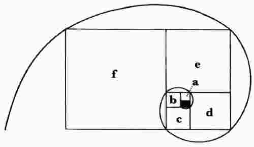
television pictures too are drawn based on a ratio.

For about the final 2/3 of each of the 525 horizontal lines in a scanning raster, a class "C" power-amplifier stage drives the three electron beams (See Right side traced by output tube's current, above). Then, when the amplifier cuts off, energy from a collapsing magnetic field drives (1) the retrace then (2) deflection for about the first third of the next line ( Left side traced by damped current , above). Here's how, but first some additional background.
FLYBACK
A flyback is a matching transformer that couples sweep energy from the class "C" power amplifier to the horizontal deflection yoke coils. In the CT-100, the flyback is an autotransformer.
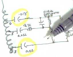
Taps on the autotransformer (pins 3 and 6 on the CTC-2 chassis flyback) match the high impedance of the horizontal power-amplifier stage to the low impedance of the horizontal deflection yoke.
Capacitors keep power amplifier plate voltage from flowing in the deflection coils. These capacitors couple the sweep energy but block the dc to keep it from affecting horizontal centering. Only the ac component is passed to the horizontal deflection yoke coils.
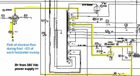
Electron flow in a CTC-2 horizontal deflection circuit during the final two-thirds of each horizontal sweep is seen in yellow highlighter, below.
TRACE-RETRACE-TRACE-RETRACE...
There are two tubes in a horizontal sweep circuit that do all the work. The 6CD6 is a beam-power tetrode operated in class C and is the active device for the horizontal sweep circuits, the high-voltage (ultor) circuit, the boost B+, and horizontal convergence circuitry. The 6AU4 is a power diode. This tube is often connected to its own floating filament voltage since during typical operation in a flyback circuit, the cathode will be at B+ and in danger of arcing to a filament running 6.3 Vac around ground. To understand the operation of circuitry associated with these tubes, it is important to know when they conduct and when they do not.
There are three distinct conditions under which these tubes operate. The conditions are the three states of a horizontal line as it is drawn on the face of a CRT. The line begins on the left, continues across the screen, and ends on the right, then gets whisked back to the left side of the screen where it started. The states are the First-Third of the horizontal line, the Final Two-Thirds of the line, and the Retrace back to the left side of the CRT.
During these conditions the 6CD6 is OFF, ON, OFF.
During these conditions the 6AU4 is ON, ON, OFF.
In a nutshell:
1. 6AU4 -- on whenever the trace is sweeping from left to right
2. 6CD6 -- on only during final 2/3 of left-to-right trace
3. BOTH -- off during retrace
SWEEP
Let's step into the fray when the electron beams are reaching the right side of the phosphor dot screen. The beams were deflected there by (1) a magnetic field developed by (2) current flow through the horizontal deflection coils that is (3) controlled by the Class "C" 6CD6 power amplifier. In the above illustration, yellow highlighter traces a path of electron flow in a CT-100 flyback circuit during this Final Two-Thirds of each horizontal trace. Below, red indicates typical current flow in a horizontal yoke during Retrace and the First-Third of the trace.
Capacitors keep power amplifier plate voltage from flowing in the deflection coils. These capacitors couple the sweep energy but block the dc to keep it from affecting horizontal centering. Only the ac component is passed to the horizontal deflection yoke coils.
Electron flow in a CTC-2 horizontal deflection circuit during the final two-thirds of each horizontal sweep is seen in yellow highlighter, below.

TRACE-RETRACE-TRACE-RETRACE...
There are two tubes in a horizontal sweep circuit that do all the work. The 6CD6 is a beam-power tetrode operated in class C and is the active device for the horizontal sweep circuits, the high-voltage (ultor) circuit, the boost B+, and horizontal convergence circuitry. The 6AU4 is a power diode. This tube is often connected to its own floating filament voltage since during typical operation in a flyback circuit, the cathode will be at B+ and in danger of arcing to a filament running 6.3 Vac around ground. To understand the operation of circuitry associated with these tubes, it is important to know when they conduct and when they do not.
There are three distinct conditions under which these tubes operate. The conditions are the three states of a horizontal line as it is drawn on the face of a CRT. The line begins on the left, continues across the screen, and ends on the right, then gets whisked back to the left side of the screen where it started. The states are the First-Third of the horizontal line, the Final Two-Thirds of the line, and the Retrace back to the left side of the CRT.
During these conditions the 6CD6 is OFF, ON, OFF.
During these conditions the 6AU4 is ON, ON, OFF.
In a nutshell:
1. 6AU4 -- on whenever the trace is sweeping from left to right
2. 6CD6 -- on only during final 2/3 of left-to-right trace
3. BOTH -- off during retrace
SWEEP
Let's step into the fray when the electron beams are reaching the right side of the phosphor dot screen. The beams were deflected there by (1) a magnetic field developed by (2) current flow through the horizontal deflection coils that is (3) controlled by the Class "C" 6CD6 power amplifier. In the above illustration, yellow highlighter traces a path of electron flow in a CT-100 flyback circuit during this Final Two-Thirds of each horizontal trace. Below, red indicates typical current flow in a horizontal yoke during Retrace and the First-Third of the trace.
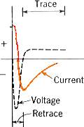
Only that part of the Trace current waveform developed by the reactive componenets is shown here.
The 6CD6 class "C" output stage will begin to conduct and supply additional current to complete the trace.
When the electron beams reach the far right of the phosphor-dot screen, the power amplifier is cut off (current no longer flows along the yellow path), which collapses the magnetic fields. The whole horizontal output circuit breaks into oscillation from the shock, and the energy in the first half-cycle of oscillation drives the three beams back to the left of the phosphor-dot screen. The three beams flyback, or retrace, (get there) in about 7 microseconds.
During the flyback/retrace time, the damper also does not conduct. Its cathode is more positive than its plate. (A collapsing magnetic field, of course, induces energy of opposite polarity to that which formed it.) But during the last half of this first cycle of oscillation, the cathode of the damper goes much less positive and the damper conducts. This effectivly prevents the oscillation from continuing, for it channels all remaining energy into developing a magnetic field to drive the electron beams from the left side of the screen toward the center. Energy drawn from this last half of this first cycle of oscillation is depleted by the time the beams are about a third of the way across the screen. The system oscillates for only one cycle per scanned line.
Energy required to scan the First-Third of a line is derived from the reactive components of the sweep circuit. Hence the name reactive (or reaction) scanning.
The class "C" power amplifier is biased to begin a new conduction period when reactive scan energy is expended.
BOOST B+

It is possible to develop a higher-than-normal "B" voltage by utilizing energy recovered from the reaction scanning circuit (during the "First-Third" state).
A capacitor (3C216 RCA; C133 Sams) is connected between +385 volts and pin 1 of the flyback. [Note that pin 1 of the 80-ohm horizontal centering pot is the actual +385-volt bus, but pin 3 of the pot is essentially also +385.]
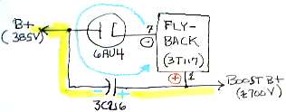
[ 10-14-02. Early in 2001, I received an intriguing email from James who was then restoring his CT-100 (CTC-2 chassis B8002239). In addition to the boost capacitor (3C216 RCA; C133 Sams), it seems an undocumented wire was connected to Pin 1 of the flyback to bus B+ voltage to other areas of the CTC-2 chassis. This was not uncommon in sets of the fifties -- B+ often powered other circuits, the vertical sweep circuit was one -- but not in the CTC-2 chassis. My own chassis, B8000173, is wired as shown in schematics with only the boost capacitor connected to pin 1. Is there a second instance of this anomaly?
06-24-05 The puzzle has been solved and documented. At a time fairly early in the production run, a design change was made to the flyback circuit. This alteration ensured that the boost B+ circuit would develop adequate energy to (1) continue to aid the horizontal sweep circuit and (2) now provide the vertical oscillator plate voltage, which had previously been supplied directly from the 375-volt low-voltage power supply bus. For some reason, documentation for this change was either inadequately covered or never included in popular service literature of the day. For my documentation of this hush-hush production change, click here .]
HIGH-VOLTAGE (ULTOR)
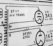
The 19,500 volts for the CRT is generated during the third state, the retrace period. The same first cycle of oscillation, that (1) returns the electron beams to the left side of the screen and (2) develops the pulse of electrical energy that makes the damper cathode positive and nonconducing (as described in SWEEP), is used to produce a pulse of energy that is applied to the flyback autotransformer. This pulse, in the neighborhood 2 kV, is boosted by the step-up turns ratio of the flyback and appears at pin 9 (connects to the 6CD6 plate) where it is then boosted to 19,500 volts by the high-voltage winding of the flyback transformer (pin 9 to top of 3T117, which is connected to the plate cap of the 3A3 H-V rectifier).
[This is a draft (posted 10-29-00) of text to accompany this CT-100 flyback-circuit graphic, and it is all under development. The page went on-line (9-3-00) in anticipation of my completing the final copy. Material added 11-4-2001, 12-16-2001; 1-2-02; 1-4-02; 3-31-02; 10-14-02; typo corrected 3-24-2003; updated 6-24-05]
