THE SETRestoration Materials6-27-99. Reference materials for CT-100 restoration.
I use schematics from two sources. Both are original schematics from that era, each with strengths and weaknesses. I also use these three books: "Highlights of Color Television", "Basic Television", and "Introduction to COLOR TV" 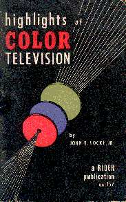 I found this publication on the counter of an electroncis parts store on Arch Street in Philadelphia when I was a teenager. It's a first edition published in 1954, and it was well thumbed and the only copy they had. I grabbed it fast and paid full price: $0.99!
There are no circuits in this booklet, it contains a smattering of superflous equations, but there are details not found in my other references. For example, the diameter of a hole in the tricolor crt shadow mask is 0.009-in. and the centers of adjacent phosphor dot trios are separated by 0.0236-in. Similar details appear in 'the 15GP22' link found on the 'simplified theory menu' page. There are some interesting vector diagrams (Fig. 11. Color difference modulating vectors) and line art with concern for detail and accuracy. (Fig 17. Relation between shadow mask and phosphor dot plate.) "Highlights of Color Television" is the first Color TV publication I acquired. It's a small, 44-page booklet by an engineer from GE's Radio and Television Department in Syracuse, who was clearly chafed by editorial restraints discouraging him from writing things like (on page 13): "Gamma itself can best be defined by writing two equations." All in all, I feel I got my money's worth. "Basic Television" by Bernard Grob. This is a second edition published in 1954. It includes a nice chapter on the new NTSC color television system. This is the casebound textbook I used in tech school for basic B&W television courses and labs. Grob and editors included an RCA schematic of the CTC-2 chassis on a 31-inch foldout. It's a great schematic and one of two I photocopied because it uses bold lines to show important signal flow: a good help when interpreting functional aspects of the circuitry. RCA engineers and drafters paid special attention to the logical, functional layout of schematics. A disadvantage of this RCA-supplied schematic became quickly evident. It is not up-to-date. It's not the production schematic. For example, the actual CTC-2 chassis uses a two-inch piece of number 26 wire in each of the two main filament buses. Whether it was designed as a crude form of surge protection or as a hedge against shorts on the filament bus is problematic. They exist in the circuit, but not on the RCA schematic. On the other hand, a positive aspect of this functional schematic can be found at the color-killer circuit. A winding on the flyback transformer develops a 100-volt positive pulse at the horizontal line rate for the plate of the killer (6AN8 triode section). The RCA schematic shows the flyback winding with reference letters that point to a clone of the coil in the plate circuit of the killer. By drawing the clone winding in series with the plate, RCA made the flyback winding function easier to analyze. And finally, in my circuit descriptions I've used reference designations from this RCA schematic because, when I started, I didn't know of its shortcoming. But there is an advantage. This schematic segments parts into functional and physical sections. A number was assigned to each major functional area. That number precedes the reference designation of parts in that section. For example, the Y matrix adder resistor in the green adder is 4R224. The Y matrix adder resistor in the blue adder is 5R326. The focus potentiometer in the horizontal and high-voltage section is 3R259. The sections as they appear on the schematic are: 1 R-F , I-F BASE 2 MAIN BASE 3 HI-VOLTAGE POWER SUPPLY 4 GREEN VIDEO BOARD 5 BLUE VIDEO BOARD 6 RED VIDEO BOARD 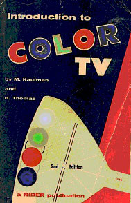 "Introduction to COLOR TV" by M. Kaufman and H. Thomas. This is the second color television reference I bought. Published by Rider, it too is a second edition, but this paperback came out in 1956 and cost me $2.70. And yes, I touched up the green and dark blue; the cover had faded considerably. This work contains later vintage schematics on its foldout. An RCA CTC-4 with the high-level R-Y / B-Y demodulation and 21AXP22 tricolor picture tube is given. As a bonus, and because Kaufman was a CBS engineer in their Color Engineering Labs, this foldout also includes a schematic of the basic CBS Model 205 with its I/Q demodulation and 19-inch
19VP22
round (or HD-266A rectangular) picture tube. This schematic illustrates how the RCA-developed design was a standard for other manufacturers. There were some make-sense alterations in the CBS version, such as the substitution of a 12AU7 for the octal 6SN7 that RCA used as a horizontal oscillator and control. And there was the needed beefing-up of the horizontal section with parallel-connected 6CU6 horizontal output tubes, two parallel-connected 6AU4 dampers, and a pair of 3A3 high-voltage rectifiers in a voltage doubler configuration. This book had the advantage of two years of development compared to the Grob, and while it has good and interesting information, it is a lightweight by comparison. The section on color killers, for example, uses simplified schematics for reference, but stops where Grob continues with a brief, but complete and useful circuit analysis.
"Introduction to COLOR TV" by M. Kaufman and H. Thomas. This is the second color television reference I bought. Published by Rider, it too is a second edition, but this paperback came out in 1956 and cost me $2.70. And yes, I touched up the green and dark blue; the cover had faded considerably. This work contains later vintage schematics on its foldout. An RCA CTC-4 with the high-level R-Y / B-Y demodulation and 21AXP22 tricolor picture tube is given. As a bonus, and because Kaufman was a CBS engineer in their Color Engineering Labs, this foldout also includes a schematic of the basic CBS Model 205 with its I/Q demodulation and 19-inch
19VP22
round (or HD-266A rectangular) picture tube. This schematic illustrates how the RCA-developed design was a standard for other manufacturers. There were some make-sense alterations in the CBS version, such as the substitution of a 12AU7 for the octal 6SN7 that RCA used as a horizontal oscillator and control. And there was the needed beefing-up of the horizontal section with parallel-connected 6CU6 horizontal output tubes, two parallel-connected 6AU4 dampers, and a pair of 3A3 high-voltage rectifiers in a voltage doubler configuration. This book had the advantage of two years of development compared to the Grob, and while it has good and interesting information, it is a lightweight by comparison. The section on color killers, for example, uses simplified schematics for reference, but stops where Grob continues with a brief, but complete and useful circuit analysis. The second schematic of my CT-100 comes from Sams. In 1963, I bought from stock "PHOTOFACT FOLDER SET NO. 252," the "First Photofact COLOR TV Folder...RCA Model CT-100" as the package proclaimed. It included a "4-page PHOTOFACT Standard Notation Schematic." This "standard notation" schematic, whatever that means, made the aforementioned color killer circuit more difficult to interpret. However, there are overwhelming advantages to this version of the schematic. They are (1) the fact that this is the production schematic and (2) that there are 45 references on the schematic (W1 through W45) to scope photos of important circuit nodes. Of course, there are dc voltage levels liberally located throughout the entire circuit. Which brings me to this final and very important point. The RCA schematic includes dc voltage levels that exist when the set is receiving a black and white broadcast. The Sams schematic includes dc voltage levels for a color broadcast. From this aggregate of information, you can reason that minus ten volts of bias cuts off the color killer triode during color transmissions, but bias rises to minus two volts (as shown here) during B&W transmissions, which allows the killer to conduct while 100-volt pulses from the flyback winding are applied to its plate. Good old Grob then completes this killer story by describing current flow when the triode conducts. It includes an otherwise obscure capacitor, 2C259, that charges to minus nine volts, a negative level great enough to cut off the chroma bandpass amplifier, which is the goal during black and white operation. (Updated 12-16-2000)
|