|
Television Experimenters.com
Which Scanner is Best?
Which Mechanical Scanner is Best? |
The first scanner, suitable for television as we know it, was invented and patented by Paul Nipkow of Germany in 1884. It became known as the "Nipkow Disk". It was first used in 1890 by an Australian, Henry Sutton for his "Telephane", which was an early attempt to get the Nipkow disk to actually work. For the next 40 years, Nipkow’s disk or one of its variations would be the favored mechanical scanning device.
In 1889, Jean Lazare Weiller introduced the mirror drum as a scanning device and two years later (1891) Louis Marcel Brillouin added lenses to the Nipkow disk, which became known as the lens disk. Although both of these ideas were soon recognized as improvements over the basic Nipkow disk, it was not until the early 1920s that these ideas began appear in proposals related to practical television.
Within a few more years, there were numerous other scanner s, both lens and aperture types and some that used slots instead of holes. There were also drum scanners, with as many variations as those of scanning disks. Mirror types of scanners included Vibrating, Polyhedral, Oscillating, Mihaly and the Mirror Screw.
By this time, engineers were being challenged to decide which scanner was "the best". To do this, they first needed to understand what was meant by "the best". This is what they might have come up with:
1: Their concern was only with the receiver. Camera scanners would have their own set of guidelines.
2: Low manufacturing costs.
3: Small cabinet footprint versus image size
4: Stable, reliable operation.
5: High light efficiency
6: Group viewing possible.
7: Picture size, 3" X 4" minimum
This would be a good start.
Let us consider the merits of some scanners types.
Nipkow: This is a family of rotating scanners including the Nipkow, drum and any sort of aperture types. The Nipkow disk was certainly the most common scanner … But why was that?
Part of the reason was that it was the first! Another important reason was because television was a new industry, manufacturing had had very little time to set up and be ready to supply customers. Much of the public became involved in the construction of the scanners themselves, because the Nipkow seemed so easy to build and it was. It did require the least amount of special skills, tools and materials. And kits made it even easier. Even cardboard could be successfully used for the disk, if one had nothing better. The story goes that John Logie Baird used a ladies hat box for the cardboard disc and one of their hatpins to punch the spiral of holes. He later went on to using plywood for the disks.
The Nipkow scanners did offer low cost with simple reliable operation, but they produced small postage stamp size pictures. Magnifying lenses could increase the picture size, but then picture brightness and viewing angles would be significantly reduced.
For larger picture sizes, disk diameters would quickly grow to unwieldy dimensions.
Lens disks: can provide large bright pictures, but at much greater cost. Lenses need to be "matched" and positioned according to their optical centers. The lens disk itself required special preparation, so it could properly support the lenses. Generally, the disk was made of a heavier gauge material and counterbored at each lens position. The lenses were purchased as a matched set and carefully installed individually, to see that the optical center of each and every lens was located exactly correct. These requirements were well
beyond the capabilities of the amateur or home constructor. In 1928, C. F. Jenkins used a 48-line lens disk in the construction of a 35mm-film type, television camera. That particular disk cost $9000. Both Alexanderson and Sanabria produced 48 and 45 line theater size pictures, with two and three foot diameter lens disks.
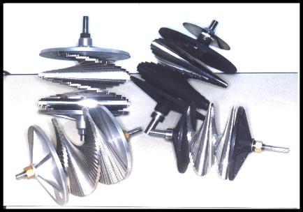
Mirror types: Generally offered good light efficiency, therefore bright pictures. Some provide a means of projection, making very large pictures a possibility. The mirror screw is unique in that without any secondary devices or attachments, it provides a picture as large as itself, with perfectly formed scan lines. The picture on a mirror screw appears to have more lines than are actually present. It is also one of the easiest scanners to use, many times being nothing more than a mirror screw mounted directly on a motor shaft. It also offers the
smallest cabinet footprint for any given picture size. Even smaller mirror screws can provide a 3" X 4" picture. However, TeKaDe built mirror screws as large as 12" X 15".
So it appears that the mirror screw might rightly be considered, the best mechanical scanner. So why was the Nipkow disk so much more common? It certainly was… Again! But why was that?
|
The Mirror Screw: The mirror screw wasn’t patented until 1928. Therefore, it was not available for the first television
boom, which occurred in that same year. That was the time when new television broadcasting stations where coming on, some with regular programming. But Manufacturers such as Jenkin’s, Western Television and others, all over the world, had already decided which scanner they would go with. With the Nipkow, there
would be no royalties involved and therefore no lawyers. Need more be said? |
|
| t was a few years later, when in 1931 Okolicsanyi became involved with TeKaDe of Germany and actually began producing television receivers using 90 line mirror screws. , (Franz von Okolicsanyi reputedly said that he had the same idea for a mirror screw in October 1927). Although the company never reached a high production rate on these mirror screw receivers, it was claimed that the cost of the mirror screws itself, in quantity could be reduced to just a few dollars. What TeKaDe appeared to may have had in mind, was to cast
the body of the screw in a material similar to Bakelite and electroplate the mirror surfaces. If a person would examine the quality of the casting work done by radio manufacturing companies, such as Atwater Kent with their knobs and tuner parts in 1931, they might agree that it would likely be adequate for the manufacture of mirror screws. Through the years, the television line rates tended to increase. Up to 180 lines, the construction of the mirror screw remained simple, but beyond that, complex attachments needed to be added on. This situation continued throughout the early 1930s, until in 1936, even TeKaDe finally went to 441 lines and at that point had to give up on mechanical television. It might be said, that for up to 180 line images, the mirror screw was the best all around scanner for mechanical television. |
The progress of television during the early 1930s could have experienced a major boost. It would have offered the public low cost sets for the home that the whole family could enjoy. Even with 90-line or 120-line operation, pictures in the 4 to 6 inch range appeared to be very clear (or sharp) and enjoyable.
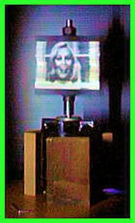
As mentioned previously, mirror screws can be attached directly onto a motor shaft and use the motor bearings for their total support. Here on the right is a mirror screw showing a bright 60-line, 3" X 4"picture while mounted on a motor, supported in a temporary stand. Larger screws, such as those used in the available Scanning Engines, usually will have their own support bearings. To learn more about mirror screws, click HERE |
 |

All rights reserved.
|