|
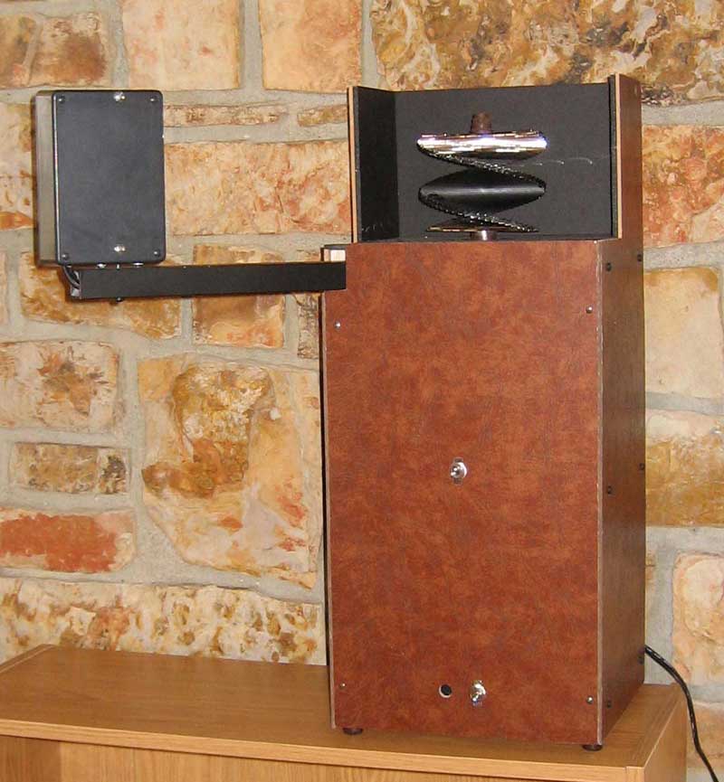
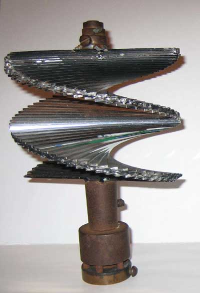
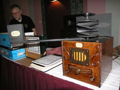
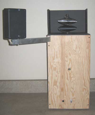
xxxxxxxxxxxxxxxxxxxxxxx xxxxxxxxxxxxxxxxxxxxxxxxxxxxxx xxxxxxxxxxxxxxxxxxxxxxxx xxxxxxxxxxxxxxxxxxxxxxxxxxxxx xxxxxxxxxxxxxxxxxxxxxxxxxxxxxx xxxxxxxxxxxxxxxxxxxxx xxxxxxxxxxxxxxx xxxxxxxxxxxxxxxxxx xxxxxxxxxxxxxxxxxxxxxxxxxxxxxxxxxxxxxxxxxxx xxxxxxxxxxxxxxxxxxxxxxxxxxxxxx xxxxxxxxxxxxxxxxxxxxxxxx xxxxxxxxxxxxxxxxxxxxxxxxxxxxx xxxxxxxxxxxxxxxxxxxxxxxxxxxxxx xxxxxxxxxxxxxxxxxxxxx xxxxxxxxxxxxxxx xxxxxxxxxxxxxxxxxx xxxxxxxxxxxxxxxxxxxxxxxxxxxxxxxxxxxxxxxxxxx xxxxxxxxxxxxxxxxxxxxxxxxxxxxxx xxxxxxxxxxxxxxxxxxxxxxxx xxxxxxxxxxxxxxxxxxxxxxxxxxxxx xxxxxxxxxxxxxxxxxxxxxxxxxxxxxx xxxxxxxxxxxxxxxxxxxxx xxxxxxxxxxxxxxx xxxxxxxxxxxxxxxxxx xxxxxxxxxxxxxxxxxxxxxxxxxxxxxxxxxxxxxxxxxxx xxxxxxxxxxxxxxxxxxxxxxxxxxxxxx xxxxxxxxxxxxxxxxxxxxxxxx xxxxxxxxxxxxxxxxxxxxxxxxxxxxx xxxxxxxxxxxxxxxxxxxxxxxxxxxxxx xxxxxxxxxxxxxxxxxxxxx xxxxxxxxxxxxxxx xxxxxxxxxxxxxxxxxx xxxxxxxxxxxxxxxxxxxxxxxxxxxxxxxxxxxxxxxxxxx xxxxxxxxxxxxxxxxxxxxxxxxxxxxxx xxxxxxxxxxxxxxxxxxxxxxxx xxxxxxxxxxxxxxxxxxxxxxxxxxxxx xxxxxxxxxxxxxxxxxxxxxxxxxxxxxx xxxxxxxxxxxxxxxxxxxxx xxxxxxxxxxxxxxx xxxxxxxxxxxxxxxxxx xxxxxxxxxxxxxxxxxxxxxxxxxxxxxxxxxxxxxxxxxxx xxxxxxxxxxxxxxxxxxxxxxxxxxxxxx xxxxxxxxxxxxxxxxxxxxxxxx xxxxxxxxxxxxxxxxxxxxxxxxxxxxx xxxxxxxxxxxxxxxxxxxxxxxxxxxxxx xxxxxxxxxxxxxxxxxxxxx xxxxxxxxxxxxxxx xxxxxxxxxxxxxxxxxx xxxxxxxxxxxxxxxxxxxxxxxxxxxxxxxxxxxxxxxxxxx xxxxxxxxxxxxxxxxxxxxxxxxxxxxxx xxxxxxxxxxxxxxxxxxxxxxxx xxxxxxxxxxxxxxxxxxxxxxxxxxxxx xxxxxxxxxxxxxxxxxxxxxxxxxxxxxx xxxxxxxxxxxxxxxxxxxxx xxxxxxxxxxxxxxx xxxxxxxxxxxxxxxxxx xxxxxxxxxxxxxxxxxxxxxxxxxxxxxxxxxxxxxxxxxxx xxxxxxxxxxxxxxxxxxxxxxxxxxxxxx xxxxxxxxxxxxxxxxxxxxxxxx xxxxxxxxxxxxxxxxxxxxxxxxxxxxx xxxxxxxxxxxxxxxxxxxxxxxxxxxxxx xxxxxxxxxxxxxxxxxxxxx xxxxxxxxxxxxxxx xxxxxxxxxxxxxxxxxx xxxxxxxxxxxxxxxxxxxxxxxxxxxxxxxxxxxxxxxxxxx xxxxxxxxxxxxxxxxxxxxxxxxxxxxxx xxxxxxxxxxxxxxxxxxxxxxxx xxxxxxxxxxxxxxxxxxxxxxxxxxxxx xxxxxxxxxxxxxxxxxxxxxxxxxxxxxx xxxxxxxxxxxxxxxxxxxxx xxxxxxxxxxxxxxx xxxxxxxxxxxxxxxxxx xxxxxxxxxxxxxxxxxxxxxxxxxxxxxxxxxxxxxxxxxxx xxxxxxxxxxxxxxxxxxxxxxxxxxxxxx xxxxxxxxxxxxxxxxxxxxxxxx xxxxxxxxxxxxxxxxxxxxxxxxxxxxx xxxxxxxxxxxxxxxxxxxxxxxxxxxxxx xxxxxxxxxxxxxxxxxxxxx xxxxxxxxxxxxxxx xxxxxxxxxxxxxxxxxx xxxxxxxxxxxxxxxxxxxxxxxxxxxxxxxxxxxxxxxxxxx xxxxxxxxxxxxxxxxxxxxxxxxxxxxxx xxxxxxxxxxxxxxxxxxxxxxxx xxxxxxxxxxxxxxxxxxxxxxxxxxxxx xxxxxxxxxxxxxxxxxxxxxxxxxxxxxx xxxxxxxxxxxxxxxxxxxxx xxxxxxxxxxxxxxx xxxxxxxxxxxxxxxxxx xxxxxxxxxxxxxxxxxxxxxxxxxxxxxxxxxxxxxxxxxxx xxxxxxxxxxxxxxxxxxxxxxxxxxxxxx xxxxxxxxxxxxxxxxxxxxxxxx xxxxxxxxxxxxxxxxxxxxxxxxxxxxx xxxxxxxxxxxxxxxxxxxxxxxxxxxxxx xxxxxxxxxxxxxxxxxxxxx xxxxxxxxxxxxxxx xxxxxxxxxxxxxxxxxx xxxxxxxxxxxxxxxxxxxxxxxxxxxxxxxxxxxxxxxxxxx xxxxxxxxxxxxxxxxxxxxxxxxxxxxxx xxxxxxxxxxxxxxxxxxxxxxxx xxxxxxxxxxxxxxxxxxxxxxxxxxxxx xxxxxxxxxxxxxxxxxxxxxxxxxxxxxx xxxxxxxxxxxxxxxxxxxxx xxxxxxxxxxxxxxx xxxxxxxxxxxxxxxxxx xxxxxxxxxxxxxxxxxxxxxxxxxxxxxxxxxxxxxxxxxxx xxxxxxxxxxxxxxxxxxxxxxxxxxxxxx xxxxxxxxxxxxxxxxxxxxxxxx xxxxxxxxxxxxxxxxxxxxxxxxxxxxx xxxxxxxxxxxxxxxxxxxxxxxxxxxxxx xxxxxxxxxxxxxxxxxxxxx xxxxxxxxxxxxxxx xxxxxxxxxxxxxxxxxx xxxxxxxxxxxxxxxxxxxxxxxxxxxxxxxxxxxxxxxxxxx xxxxxxxxxxxxxxxxxxxxxxxxxxxxxx xxxxxxxxxxxxxxxxxxxxxxxx xxxxxxxxxxxxxxxxxxxxxxxxxxxxx xxxxxxxxxxxxxxxxxxxxxxxxxxxxxx xxxxxxxxxxxxxxxxxxxxx xxxxxxxxxxxxxxx xxxxxxxxxxxxxxxxxx xxxxxxxxxxxxxxxxxxxxxxxxxxxxxxxxxxxxxxxxxxx xxxxxxxxxxxxxxxxxxxxxxxxxxxxxx xxxxxxxxxxxxxxxxxxxxxxxx xxxxxxxxxxxxxxxxxxxxxxxxxxxxx xxxxxxxxxxxxxxxxxxxxxxxxxxxxxx xxxxxxxxxxxxxxxxxxxxx xxxxxxxxxxxxxxx xxxxxxxxxxxxxxxxxx xxxxxxxxxxxxxxxxxxx Mechanical Television Color Mirror Screw Project The completed mirror screw scanner A few months ago we acquired a pair of mirror screws used by Bell Labs in early 30s television experiments. At the time my plan was to use the larger screw as part of a working receiver, which could demonstrate the remarkable performance of the mirror screw for museum visitors. I will report the progress on the project here. I would appreciate comments on and suggestions for the project. For more on the history and technology of the mirror screw, see Peter Yanczer's site. This would require a 1200 rpm synchronous motor and a light source, which would be made of a row of LEDs, arranged vertically, and located about 6 inches from the screw. My plan was enclose it in a clear plastic cabinet so all the components would be visible. Later, I had discussions with Darryl Hock about the possibility of making the mirror screw display color images. He said that he could make a custom Aurora converter, which would output red, blue and green 60 line video signals. At that point I decided that the display at the museum would be both mono (orange) and in color. The image would display all three colors simultaneously, not sequentially as in the Baird mechanical color system of the 20s. The light source would have a set of LEDs for each primary color: red, blue and green. Video from the Aurora converter would be amplified and used to drive each set of LEDs. With a mono display, a row of 3 mm diameter red LEDs can be stacked on top of each other, with a diffusing material in front to make the light more uniform. Since the screw we have is 4.75 inches wide, the 3 mm width of the LEDs would result in a horizontal resolution of about 40 lines (4.75 inches = 121 mm. 121/3 = 40). However, the LED row can be masked to make a slot about 1 1/2 mm wide, which would result in about 80 lines of resolution. Here is a mirror screw receiver built by Peter Yanczer, showing the screw and the light source box: If 3 mm LEDs were used, stacked vertically with alternating red, blue and green LEDs, it would be very difficult to use a diffusing material to even out the color (red LEDs would be 9mm apart, etc.). The solution I have chosen is to use larger, 5 mm LEDs located on a separate chassis, with .75 mm diameter fiber optic cables going from the top of each LED to the light source box, where the fiber optic cables will be stacked vertically, alternating red, blue and green. The height of the light source box should be about 20% more than the height of the screw, which is 3.5 inches. Our light source should be about 4.2 inches (107 mm) high. Using .75 mm fiber cables, about 144 fibers will be needed, (48 per color). It is possible that no diffusing material will be needed. The advantages of this approach are that 1) a much brighter image is possible, because of the use of superbright LEDs; 2) the size of the light beam leaving the light source box is small enough that a diffuser won't be necessary; and 3) the width of the beam will be only .75 mm, allowing a horizontal resolution of 170 lines. I've ordered sample LEDs and some fiber optic cable to experiment with how to attach the cable to the LED. I'll use a light meter to measure the efficiency of the attachment, experimenting with different ways of attaching the fiber ends to the LED. Here are the specifications for the red, blue and green LEDs I've ordered. I've received the LEDs, fiber optic cable, and light meter. In experimenting with them, I've discovered that the amount of light that enters the fiber is determined by the area of the cross-section of the fiber. With .75 mm fibers, the area is about .44 sq mm. The area of the face of the 5 mm LED is about 19 mm. Therefore, only about 2.3% of the light from the LED enters the fiber cable. However, I also discovered that at least 12 fibers (my fibers are bundled with 12 in a sheath) can be illuminated by a single LED. I suspect that the amount of illumination coming from each fiber will not be enough to get a very bright image on the mirror screw.
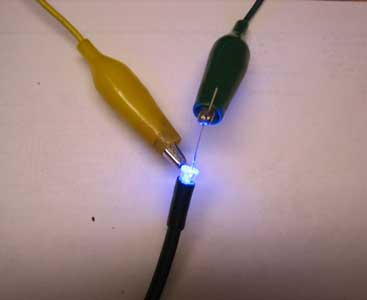
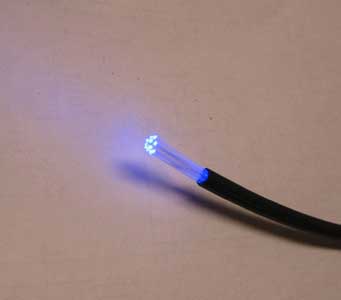
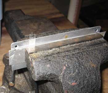
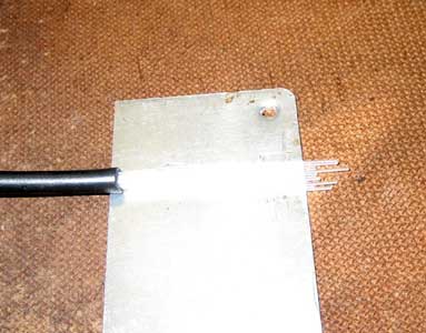
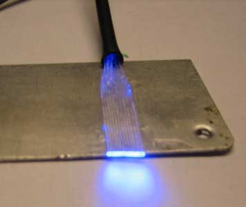
There are three ways to improve this that I can think of. First, a small lens could be used in front of each LED to focus the light into a single fiber (or group of fibers). The second approach would be to sacrifice horizontal resolution and put two rows of fibers in the light source aperture. The final idea I came up with is to use 1 watt LEDs, which put out much more light. I think the lens approach is too cumbersome. The two row fiber approach would result in twice the light output, but using the 1 watt LEDs should result in about 15 times more light than the superbright LEDs I've tested. I've ordered some 1 watt LEDs. The 1 watt LEDs are also 5 mm in diameter and have about a 100 degree beam width. I will experiment to see how many fibers I can attach to a single LED and still have reasonably uniform light output into each fiber. Today I experimented with gluing the fibers to a metal plate to make the light source.
Finally, I used a hot razor knife to cut the fiber ends off. The next row of fibers will be affixed directly to the left of these. I did some light intensity measurements. First I measured the output of the blue LED, placed 1/2 inch from the light meter. I recorded 1900 lux. With the fiber bundle attached to the face of the LED, I measured the output of the bundle of 12 fibers (all measurements are 1/2 inch from the meter) at 390 lux. The light output from a single fiber was 33 lux. The spec sheet for the meter shows the the meter's sensitivity at 467 nm (the dominant wavelength of the blue LED) is about 65%. In order to compare this output to that of the other LEDs, I have corrected the above readings to 2923 lux, 600 lux, and 51 lux. I received the 1 watt LEDs and measured the light output of the fiber bundle. With 150 ma current (50% brightness - I don't have a power supply handy that can put out the 300 ma for full brightness) I measured 1900 lux. Correcting for the color sensitivity of the meter, the adjusted output is about 2900 lux. At 100% brightness the LED should produce 5100% lux, about ten times the output using a superbright LED. This should be plenty bright for the mirror screw. After further experimentation, I determined that 12 fibers is all that can be easily attached to each LED and still have maximum brightness and uniform illumination of the fibers. So, the final configuration will be 12 LEDs (4 per color), with 12 fiber bundles of 12 fibers each. 2 LEDs will be driven by each op amp, for a total of 6.
I had originally planned to mount the light source on an extension arm, about 18 inches from the screw. However, Peter Yanczer explained to me that it wouldn't work:
So, the light source, Aurora converter, and LED drivers will be located in a separate housing that can be placed several feet away.
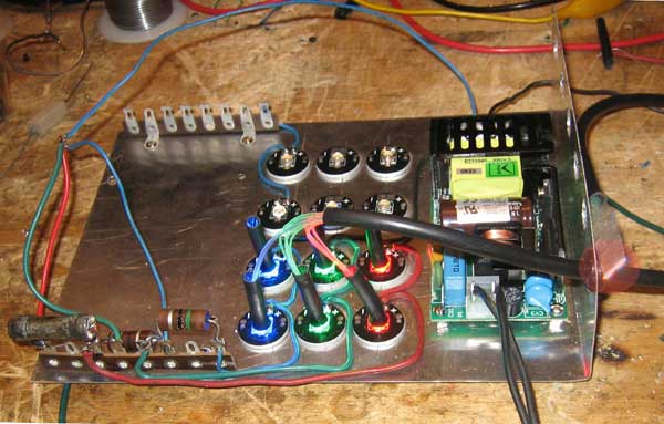
More progress on the LED/driver assembly. I have glued small plastic tubes (actually the outer cover removed from RG-59 coaxial cable) to each LED, making sure the glue was on the outside of the tubes only. I've taken the first bundle of 12 fibers, which I had previously flattened and glued together (the end of the bundle is visible at the right of the chassis, with a red circle around it). Because the fibers are quite stiff, I'll need to add some sort of support to keep the entry into the LEDs upright. The light coming out of the LED bundle looks close to white. I've now glued 36 of the 144 fibers to the board that will become the light source. I have built a support bracket to hold the fiber bundles:
I made a first attempt to bundle the 36 fibers into alternating red, green and blue groups of 12. After sorting the fibers, I tried to use heat shrink tubing to hold the groups together. However, I discovered that the fibers melt at just about the same temperature as the heat shrink, damaging a number of them. Here is the jig I use to sort the fibers:
After sorting and wrapping the bundles with tape I discovered that somehow the first 12 fibers emit almost no light. So, I'll have to unglue that bundle from the board and glue a new one on, then sort again. Hopefully I'll get the knack of this at some point.
I've finally learned how to glue the fibers to the board, sort them into the right colors, and mate the bundles with the LEDs. Here is a picture of the first 36 fibers. Next I'll complete the other bundles.
Tonight I completed 72 of the 144 fibers and decided to test the light source using a standard version of the Aurora converter (monochrome). I was finally able to get half a picture on the mirror screw, but the light source needed to be about a foot from the screw to get a single image. If I move the light source further away, there are two images side by side.
However, the picture was very poor, and the individual fibers were quite visible. Even with a mono picture, containing all three primary colors, the fibers were very objectionable. I suspect that with a color picture, where some parts of the image contain one one color, the problem would be even worse. I've concluded that some sort of diffusing material is needed to blend the light from the fibers together. However, the diffusing material would have to be a distance away from the ends of the fibers to avoid hot spots of colors. This arrangement would result in significant light loss.
Steve Ostler has proposed another way to make the light source (from vintage-radio.net):
I've concluded that Steve Ostler's approach will work, but only if a diffusing glass or rod is used at the slit. Here is what I am going to try next. Find the brightest 5mm LEDs I can get, with the narrowest angle. I will make three vertical rows of LEDs, red, green, and blue side by side, 24 LEDs high (4.8 inches) . This assembly will be placed in a box about 5 inches high, 3 inches deep and 2 inches wide. The LEDs will be placed on one of the 5 x 2 inch sides. On the other 5 x 2 inch side I'll cut a slit about 1mm wide and 4 1/4 inches long. Over this slit I'll place a diffusing material, such as ground glass. I'll mount the red and blue LEDs at a slight angle, so that the center of their beam will hit the slit. I've ordered some 5mm LEDs that have very high light output (9000 mcd for the blue, 14,000 for the red, and 16,000 for the green). They require 100 ma for full output. I'll parallel 4 groups of 3 LEDs in series and drive them from one op amp. Two op amps will be required for each color (2 groups of 12 LEDs), so the circuit I've already designed will work to drive the LEDs. I think that the easiest way to drive the LEDs is to use high power op amps. A total of 6 op amps, 2 per color, will be required. I have selected the TCA0372 dual power op amp for the project. It has a 1 amp output capacity, operates on a single power supply, and a gain-bandwidth product of 1.1 mHz. Since the Aurora converter will have an output of 1 volt video, I only need a gain of about 4, so with a 100 kHz video bandwidth I should have no problem. The other advantage of this chip is that two op amps are in an 8 pin DIP, easy to work with on a prototype board. The spec sheets show the following characteristics for the new 100 ma LEDs I've chosen Red
Green
Blue
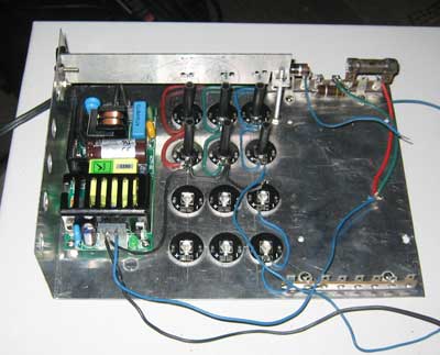
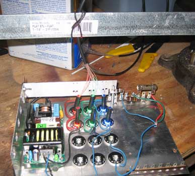
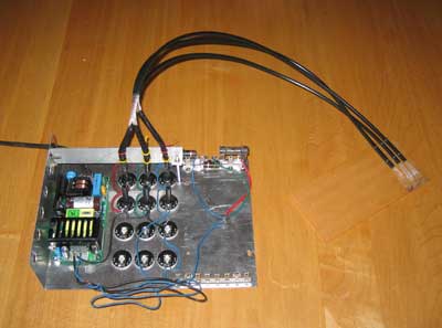
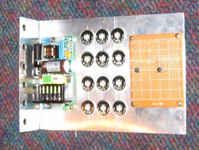
In order to get a relatively linear light vs. voltage response, the LEDs need to be driven by the op amps through a resistor. For better efficiency, it makes sense to put the LEDs in series, so less power is dissipated in the resistor. With two LEDs in series, the voltage across the LEDs would be 7.2 for the green and blue, and 4.8 for the red. The op amp can be run from a 12 volt power supply and still have sufficient voltage swing for the LEDs and the drop across the resistor. Since the LEDs won't start putting out light until the forward voltage reaches 1.9 (for the red) and about 3 (for the green and blue), the op amps will need a DC offset so that the video input of 0 volts results in an output of 3.8 volts for the red and about 6 volts for the green and blue. In order to get proper white balance, I think I'll need two pots per color - one for the DC offset, which would set balance at low levels, and one for gain, which would set balance at full output. Since I want to operate the mirror screw in both a mono (orange image) mode, and a color mode, I need to figure out some way to combine R, G and B video signals to produce an orange color, and to switch between this input and a normal R, G and B input for color. The power supply for the op amps/LEDs needs to be 12 VDC at about 5 amps. I have drawn a preliminary schematic diagram of the circuit. I'll use an L shaped metal chassis, with the bottom portion about 6 x 8 inches, and the side 6 x 2 inches. the LEDs, circuit board and 12 volt power supply will be mounted on the bottom, with holes for the fibers on the side. Here is the chassis. The 6 holes on the left are for the fiber optic cables. Next is the 12 volt power supply, then the Red, Green and Blue LEDs, and finally the prototype board for the op amp drivers. Today I tested the op amp circuit and made some minor changes, which you can see on the schematic. The most significant change was to the color/mono switch. Rather than mixing the R, G and B video signals to get white, I'm using the Y (mono) output from the Aurora, and switching the red, green and blue op amp inputs to that line for mono operation. I did some preliminary testing to see how linear the light vs. input voltage is. With the offset set so that the LED is completely out, the linearity was fine down to about 20% of voltage, but very non linear below that. By setting the offset to have the LED put out a small amount of light (2%), the response is very linear over the entire range. Blue LEDs
Darryl Hock commented on my LED driver design:
Based on these suggestions, I modified my driver. Here is the revised schematic. The linearity of light vs. input voltage is about the same as before, but this should eliminate potential temperature drift problems. I've arrived at a final design for the LED drivers. Here is the schematic.
Darryl has proposed the following design:
Our mirror screw should be capable of about 170 lines of horizontal resolution. The Aurora produces 180 pixels per line, which is just right. The screw is 4.75" wide by 3.5" high, indicating an aspect ratio of 4/3. The RCA 60 line receiver has an aspect ratio of about 1.1/1. The Aurora will need to be modified to produce a 4/3 ratio, which Darryl says is no problem. More from Darryl on the design.
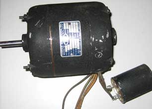
Darryl has finished the unit, and built a light source for his 60 line mechanical set: Another issue that has come up is the need for some sort of phasing arrangement, to horizontally "frame" the image on the screw. Peter Yanczer's design has a way of rotating the motor, but that is cumbersome. The Aurora converter has a pushbutton on the front that changes the phase. This should work to frame the image. 1200 rpm synchronous motors are very hard to find and expensive. I have an 1800 rpm motor left over from another project, so I've decided to use it with pulleys and a belt to reduce the speed of the screw to 1200.
The motor has a 3/8" shaft.
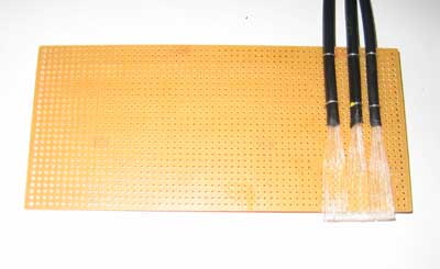
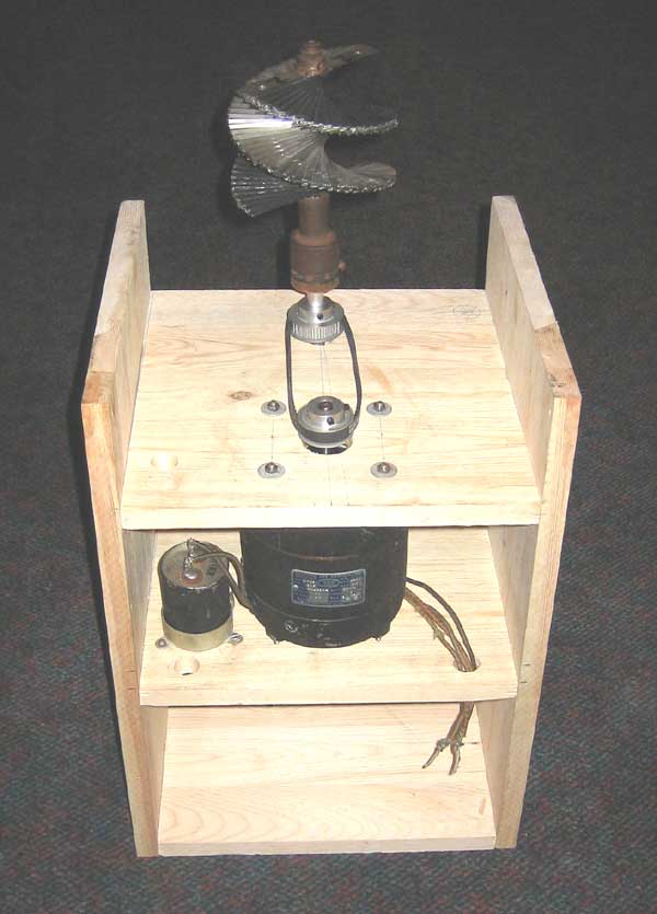
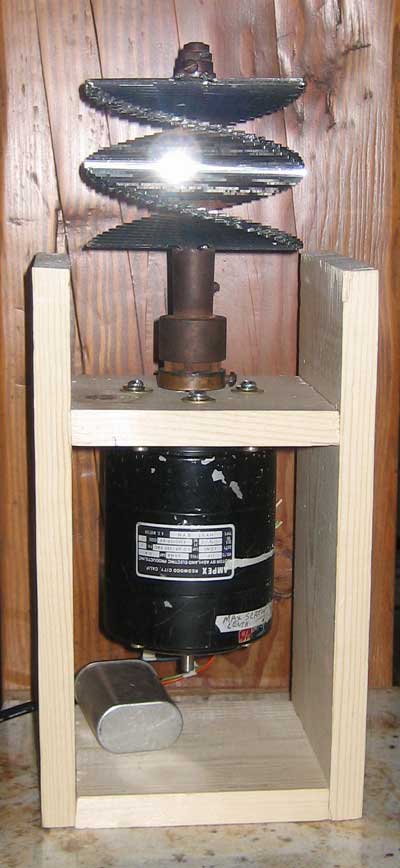
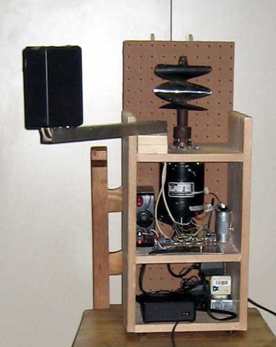
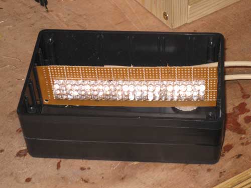
The mirror screw usess a 1/2" shaft. I've ordered one 9" long and two bearings Here is the frame I've built to hold motor and mirror screw. The LEDs, op amps, power supply, and the Aurora converter will go in a separate housing, since the light source must be several feet from the mirror screw. In the middle is the 1800 rpm motor and starting capacitor. On top is the reducing pulleys and belt. A 1/2 inch shaft will be inserted where the rear pulley is located. It will be secured with bearings (located in the middle space) and will extend about 3 inches above the pulley. The mirror screw will be mounted on top of it. I've tested the assembly, and have discovered that my motor is not synchronous. It will not lock to the power line, and turns at about 1750 rpm. Also, the assembly is very noisy. So I've decided to buy a 1200 rpm motor from Peter Yanczer. Peter's motor has arrived, and I've built a new, much smaller frame for it. There will be a top cover to hide the pulley arrangement. The front cover will have a power switch on it. Final Design Now that I have determined that the proper location for the light source is about 12-16 inches from the screw, I've gone back to the original design of putting the LED drivers and power supply below the motor. I'll put the light source on an arm extending out from the top of the housing, like Peter Yanczer did in his design. I've made the frame about 20 inches high, with the bottom compartment about 6 inches high. In the bottom compartment I'll put the Aurora converter. In the middle compartment is the motor, LED driver circuit, and 12 volt power supply. Above the top shelf is a 1 x 1 aluminum tube that holds the light source. I had a problem with vibration because the mirror screw isn't exactly balanced. The top of the screw wobbled about 1/32 of an inch. I was able to eliminate most of the wobble by adjusting screws at the bottom of the mirror screw. Then, I put rubber washers on the motor mounting bolts, drilled a larger hole in the wood, and put a piece of plastic tubing around the bolt. This virtually eliminated the remaining vibration. I've assembled a box for the LED arrays. I used a 4 x 6 x 2 inch plastic box from Radio Shack. The LEDs are mounted on a piece of vector board, the put at the rear of the case. At the front I've drilled a line about 1/8 inch wide. Over this I've placed a piece of frosted cellophane tape (for a diffuser) and plastic electrical tape to narrow the slot to about 1/16 inch wide. The slot is visible at the bottom of this picture. There are a total of 24 LEDs for each color.
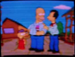
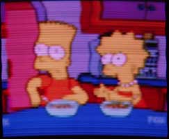
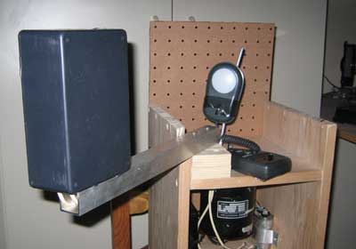
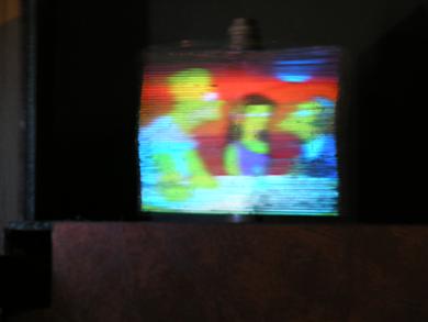
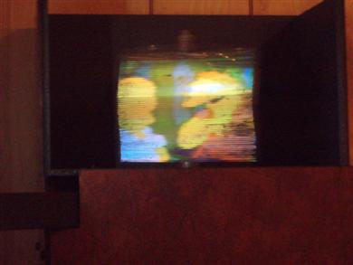
Next I'll optimize the light box. I've determined experimentally that a slot of about 1/16" wide results in decent horizontal resolution. A smaller slot doesn't significantly increase the picture quality, but the light output diminishes as you reduce the width of the slot. In the photo below you can see the arrangement for measuring light output from the light source. The mirror screw is removed, and sensor for the light meter is put in its place: With a test video signal, and the color balance adjusted approximately right, I read about 56 lux with a 1/16" slot. I've experimented with the placement of the LEDs in the box, moving them closer to the slot, and this resulted in no significant difference in light output. Next I'll experiment with a different diffusing material (donated by Darryl Hock), and with mirrors placed inside the box to direct light leaving the sides of the LED assembly and focusing it on the slot. With the present diffuser (cloudy cellophane tape), here are some photos:
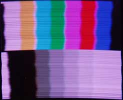
The image actually looks much better than the photos, but there are still several defects. First, notice the black areas on the right side. When I painted the screw's back, I got some black paint on the edges of the mirror surfaces. This will have to be cleaned off. There are also many areas on the screw surface that are dirty. I need to completely clean each of the 60 mirrors and polish them. Finally, the screw was apparently dropped at some point, and the image from the upper right is distorted. You can see that the scanning lines (mirror surfaces) in that area of the picture are not straight. I've straightened the mirror surfaces, but in the process they became separated (the plates were welded together). I will try gluing them back together. You can also see in the color bars that the alignment of the mirrors is off, probably from the screw being dropped. It won't be possible to fix this without disassembling the entire screw, which I don't plan to do. I also need to do a better setup of the color balance at minimum and maximum brightness. I will use a test signal generator to do this, creating a 0 luminance test signal to set the offset controls on the LED driver, and 100% luminance signal to produce a white image. I've used the test generator set up the color balance. First, I determined that the green LEDs were operating at the highest current when the picture looked white at 100% luminance. Then, using a grey scale test pattern, I put a scope across the voltage dropping resistor to the green LEDs. I then adjusted the green gain to produce a waveform that wasn't clipped at the 100% luminance. Then, I adjusted the red and blue gains to produce white at 100% luminance. Then, I used a black test pattern, and adjusted the red, green, and blue offset controls so that the LEDs were just below the point where they were emitting light. Then, I went back to check and touch up the white balance at 100% luminance. Next, I experimented with installing mirrors on either side of the LED assembly, to the slot, to see if I could increase the light output from the slot. I determined that I did gain a significant amount of light, so I built this assembly in the lid of the light source. I also mounted a mirror in the back of the light source box:
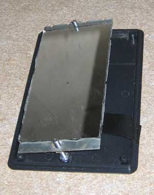
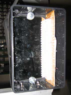
The mirror is glued to a piece of sheet metal, which has two #8 nuts soldered to it. Bolts are put through the cover, with friction nuts on the other side. The friction nuts are tightened to allow the assembly to tilt. I tightened the screws to pull the mirror toward the cover, then installed the cover. Then, I loosened the screws to move the mirror in. The edge of the mirror on the right seated against the LED assembly, and the edge on the left moved in toward the slot. At the optimum location, I got an increase in light from 56 lux (no cover) to 78 lux, an improvement of about 40%. I then installed the mirror in the back of the light source box. The light output increased to about 104 lux, almost twice the original level without the mirrors. I tried replacing the frosted cellophane tape with a piece of tracing paper, but the light was reduced from 104 lux to about 50. I then tried a piece of satin cellophane tape. I got much more light out, but not a good enough diffusion of the LEDs. Finally, I tried a piece of the plastic material that Darryl Hock sent me, but got only about 25 lux. So far, the frosted cellophane tape works best. Finally, I am making progress on polishing the scuffed areas of the mirror screw. I got some chrome and stainless steel buffing compound from an auto store, and using a Dremel tool with a cloth wheel I was able to get the shine back to normal on a portion of the screw. It is hard to get into some areas of the screw. A local jeweler told me that she has the tools to polish the mirror screw, and I'm going to take the screw her next week. Next I'll add a black background behind the mirror screw, and work on making the unit look nice. I've put a black light shield on the back and sides of the screw, and installed a plywood front cover. At the bottom you can see a hole, through which the phasing button on the Aurora converter can be pushed. Next to it is the power switch. In the center, above these, is the color/mono switch. I wasn't able to find a 3PDT switch locally to connect the three inputs to either the Y output or the R, G, and B outputs from the Aurora, so I used a 4PDT 12 volt relay. I've also installed a an adjustment screw to tilt the light box to make the image vertical (visible about 2 inches in from the end of the arm). The final step is to install plywood on the sides of the cabinet, trim, and paint the cabinet.
|
