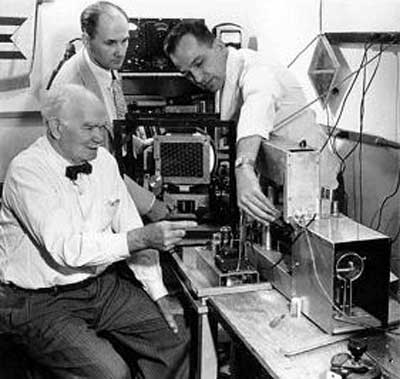
While I was a student at American Television
Institute of Technology in Chicago in 1947-1949 on the G.I. Bill of
Rights, I was introduced to Dr. Lee DeForest who was then one of
the directors of ATIT.
DeForest is, of course, the man who put the control grid into the
vacuum tube in 1905, thus creating the first signal amplifying
device.
I was a senior TV engineering student in 1949 and already had a
decade of radio and TV technician experience behind me.
DeForest (a tall, white haired dignified-looking gentleman then about
72 years old) had asked for a student who might want to work with him on
resurrecting his pre-WWII medical diathermy machine production company.
Someone in the faculty picked me and sent me to his office.
After a brief but congenial interview DeForest and I went into his
private lab. He sat down at the bench and showed me an
electro-mechanical color TV display device he was working on. It
consisted of two plates: One was a fixed, thin plate about 6 x 8 inches
with an array of horizontal and vertical apertures (small holes) in a
rectangular grid. The other plate was supported at each of its four
corners by a four rotary joints which allowed the plate to be rotated
through the vertical plane by a very small amount. The diameter of the
circle described by any spot of the rotating plate was approximately the
same as the center-to-center distance between the apertures on the
stationary plate. I do not recall exactly of what material the rotating
(gyrating) plate was made. It may have been a glass plate screened with
black opaque ink. That black opaque surface was pieced by a rectangular
pattern of tri-color, transparency spots (RGB). I assume that there
were about 400+ vertical RGB group transparencies and perhaps 500+ in
the horizontal direction (for a 400 V by 500+H pixel display in today's
terminology).
When the gyrating plate was set into motion, light from behind it would
sequentially pass through one color filter at a time and then through a
corresponding stationary aperture in the fixed plate. Hence a
field-sequential color display was generated when this mechanical array
was placed in front of a B&W CRT with a standard NTSC 441-line raster
displayed on its screen. Thinking about the details of this scheme, the
color apertures must have been 120 degree segments and progressively
rotated (in the process of making the artwork that was used to produce
the screen with which these transparent dye colors were probably
screened on) so that a portion of the the same color "triangle was still
passing over the fixed aperture, depending on which "horizontal line" of
aperture the CRT's illuminating spot was located.
I never saw this apparatus actually working. It was clearly intended to
solve the problems generated by the huge scanning discs or drum such as
those used on earlier mechanical systems and later in the CBS
field-sequential system. Clearly, moving a thin plate at 60 RPS through
a very small circular motion required very little mechanical (motor)
power. However, one look at the hardware and it appeared to me that the
optical inefficiency of DeForest's ingenious mechanical color-wheel
substitute had to be such as to doom this approach. I don't remember
whether I had the presence of mind (or the nerve) to question the
walking legend about just how he expected to overcome that
problem. Perhaps I figured that an extra bright CRT might just have
enough light output to make this system work.
I would be interested to learn if anyone (perhaps an old-timer such as
myself) knows of Dr. DeForest's color display device and what happened
to it. It would be interesting to know whether it was ever publicly
demonstrated and whether of the unit that I saw in the lab that day in
1949 had survived and found a home in some collection or museum.
[The above photo shows] DeForest sitting at a lab bench at American
Television Labs along with (I believe) John Sanabria (on the right), the
brother of ATL & ATIT president Ulysses A. Sanabria and another
engineer.
And what are they working on? The color TV scheme, of all things! If
you will look at the attached photo and blow it up, you will see that
the engineer on the left has his hand inside a open (no case) TV monitor
with what looks like a 10" or 12" CRT, probably making an adjustment.
Immediately in front of the CRT is the two-plate color scanning device I
described and hadn't seen for 55 years.
The long gear on the bench has to be a complementary signal generation
device producing field-sequential picture as a test signal source which
the setup at the rear reproduces. The signal generation device probably
use a color wheel which would be entirely practical solution for a
system with a small TV pick-up tube. (I have built sequential color TV
systems with RGB color wheels myself and they work very well when there
isn't too much motion. The first RCA cameras that went to the moon were
of that type, too).
|