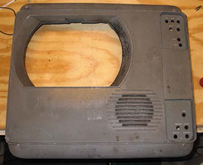
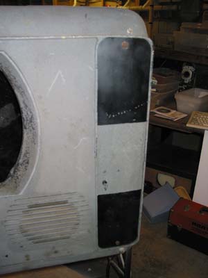
This is the front cover, made of cast aluminum. The speaker and
magnifying lens are mounted to it.
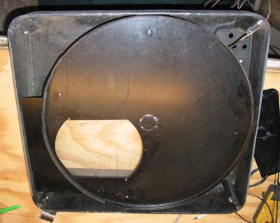
Rear view of the cover, showing the shroud for the color wheel. The
shroud is fitted to the front cover using four pins with springs around
them. The springs press the shroud firmly against the front of the main
cabinet.
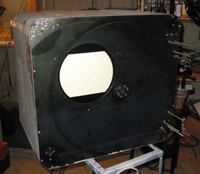
This is the front of the main cabinet. Note the hub in the middle for
the color wheel.
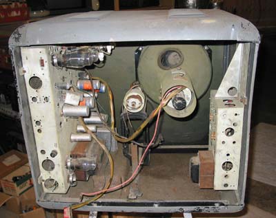
A rear view of the cabinet. On the right is the motor control chassis.
In the center is the motor mount, and on the left is the main chassis.
The CRT is a 10FP4.
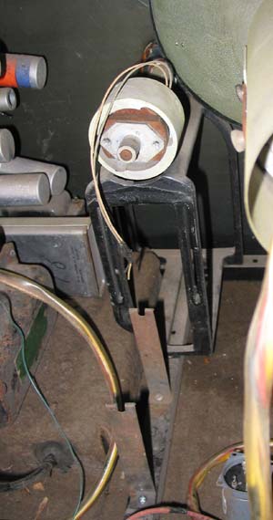
Here is the motor mount. In the front are two clamps for the starting
capacitor. Directly behind is a frame for the motor, which was mounted
behind it with the shaft facing forward. A belt drive was used to
connect the motor to the color wheel shaft (above), which has the
alternator (used to generate a signal for motor sync) mounted on it.