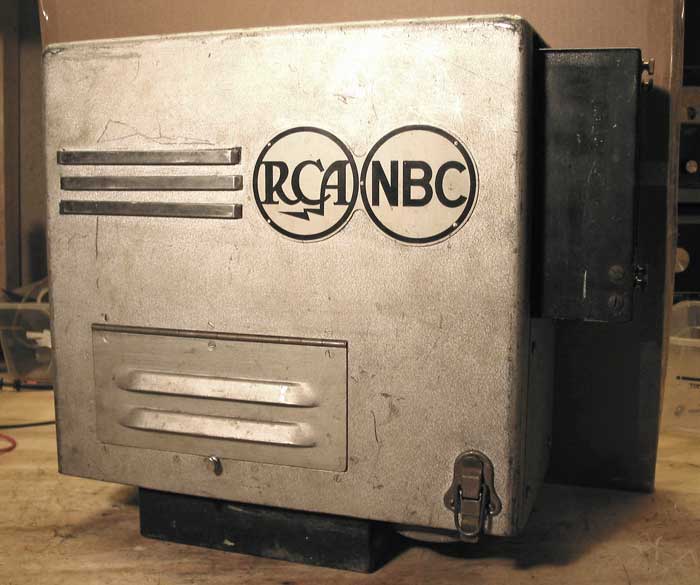
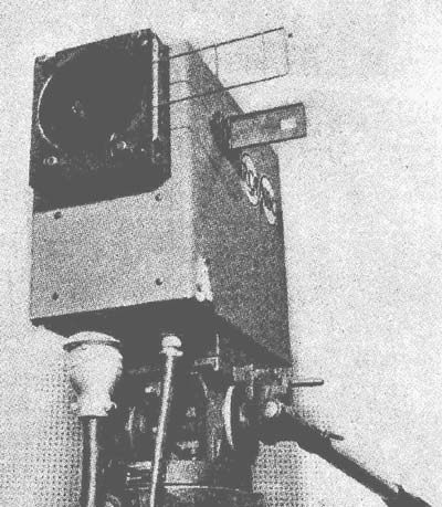
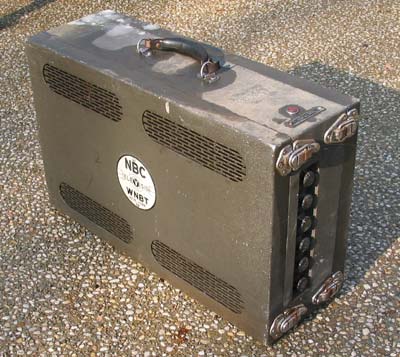
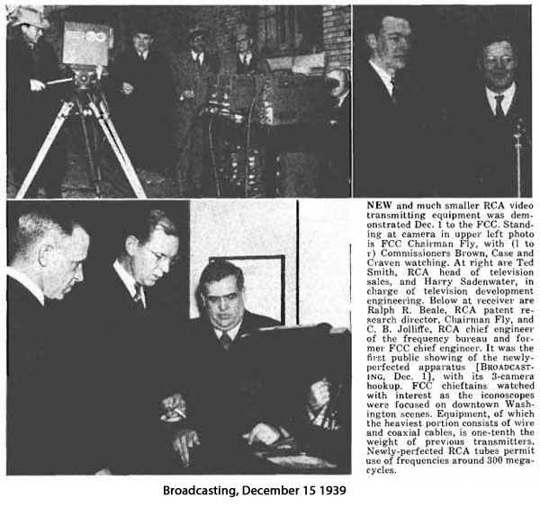
This camera was used for field pickups by RCA in 1939. It has its
original tripod and lens. (From the Danny Gustafson Collection). It is
described in detail in Vol. III of RCA's Television engineering series,
published in 1946. This was RCA's second generation of portable
television equipment. The first system required two full size busses to
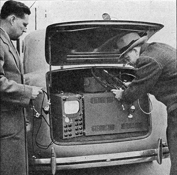
carry the equipment. This system could be carried in a van. The first
television transmission from an airplane used this equipment.
Our camera is serial number 1001, indicating that it was the first one
built.
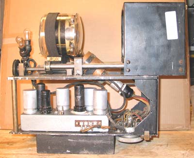
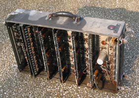
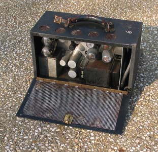
Here is a view of the camera with the cover off. It uses the 4 1/2 inch
1848 iconoscope. On the right is the lens holder. It is mounted on a
track, and is moved in and out to focus the image with a pair of servo motors.
One was in the camera
(missing) . The pulley for the motor is visible on the left, just above
the brass support. The other was in the Camera Control Unit, where
the engineer focused the camera by watching the video monitor. On the
left are two bias lamps. Below is the
video preamplifier chassis. The one in our camera is a replica, with no
components under the chassis.
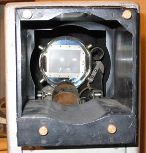
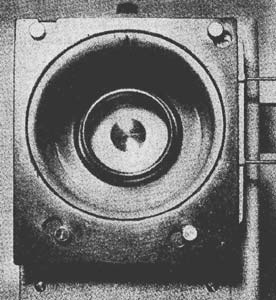
Here is a view of the front. In the middle the face of the iconoscope is
visible. The lenses were interchangeable, mounted by the 4 thumb screws.
Notice the wire frame viewfinder on the right side of the lens holder.
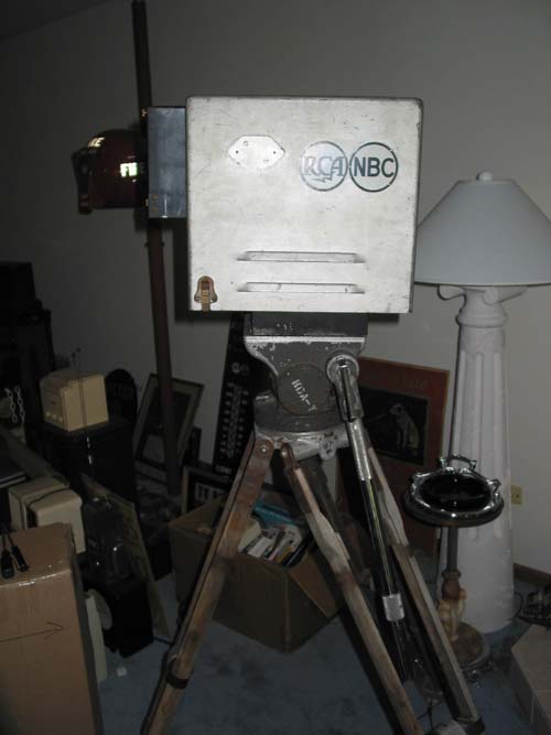
The front of the camera, showing the frame viewfinder
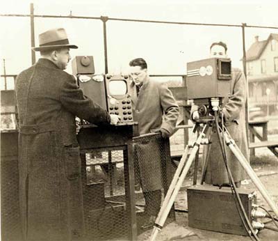
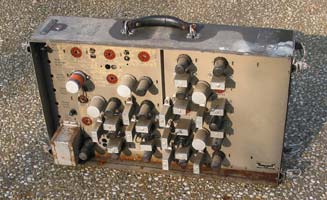
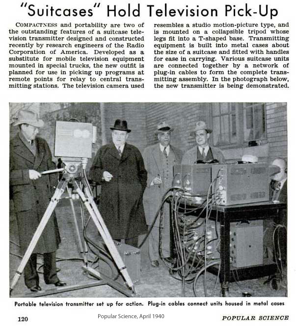
The camera, with the Camera Auxiliary Unit (under tripod) and the Camera
Control Unit.
Courtesy of Darryl Hock
The complete system consisted of the camera, an Auxiliary Control unit,
Camera Control Unit, Pulse Unit, Pulse Shaper unit, and several power
supplies. There was also a VHF transmitter that was used to relay the
signal to RCA's studio in New York.
The Auxiliary Control unit (left) has a 4 tube video amplifier and the
deflection circuits for the iconoscope. An 8 foot cable connected this
unit to the camera. Up to 500 feet of cable could be used between the
Auxiliary Control unit and the Camera Control Unit (right). It contained
a video and waveform monitor, and the controls for the iconoscope tube.
Both of these items are missing in our system.
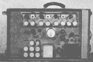
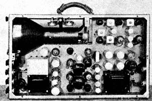
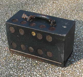
Here are pictures of the Pulse Unit. The synchronizing pulses were
created here, using countdown circuits.
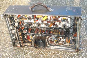
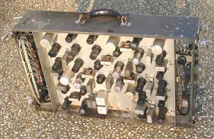
This is the Pulse Shaper Unit. Sync and blanking signals were generated
here.
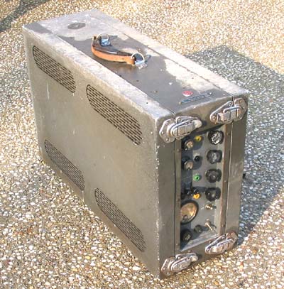
The Power Supply Unit. Apparently one was used for each of the above
units.