Early Television  
Mechanical TV History How it Works Mechanical Sets at the Museum Gallery Database Summary Broadcasting Technical Inforation Restoration Advertising Articles Roger DuPouy's Site Peter Yanczer's Site Gerolf Poetschke's Site Eckhard Etzold's Site
Early Electronic Television History American Sets at the Museum British Sets at the Museum Gallery Database Summary Broadcasting CRTs Other Equipment Technical Information Restoration Advertising Articles Gerolf Poetschke's Site Eckhard Etzold's Site
Postwar American TV History American Sets at the Museum British/Europen TV History British/Europen Sets at the Museum TV in the Rest of the World Gallery of Unusual Sets Broadcasting CRTs Other Equipment Technical Information Restoration Advertising Articles Eckhard Etzold's Site
Early Color TV History Sets at the Museum Gallery Database Summary Broadcasting Technical Information CRTs Restoration Advertising Articles Pete Deksnis's Site Ed Reitan's Color Television History Eckhard Etzold's Site
The Early Television Foundation About the Museum Directions to the Museum Articles about the Museum Support the Museum Join our Email List Our Newsletter - "What's New in Old TVs" Equipment Donations Museum Members and Supporters Members Only Monthly Online Meetings Annual Convention Swapmeets
What's New on the Site Classifieds Parts for Sale Resources Search the Site
Contact Us Facebook YouTube Channel

xxxxxxxxxxxxxxxxxxxxxxx xxxxxxxxxxxxxxxxxxxxxxxxxxxxxx xxxxxxxxxxxxxxxxxxxxxxxx xxxxxxxxxxxxxxxxxxxxxxxxxxxxx xxxxxxxxxxxxxxxxxxxxxxxxxxxxxx xxxxxxxxxxxxxxxxxxxxx xxxxxxxxxxxxxxx xxxxxxxxxxxxxxxxxx xxxxxxxxxxxxxxxxxxxxxxxxxxxxxxxxxxxxxxxxxxx xxxxxxxxxxxxxxxxxxxxxxxxxxxxxx xxxxxxxxxxxxxxxxxxxxxxxx xxxxxxxxxxxxxxxxxxxxxxxxxxxxx xxxxxxxxxxxxxxxxxxxxxxxxxxxxxx xxxxxxxxxxxxxxxxxxxxx xxxxxxxxxxxxxxx xxxxxxxxxxxxxxxxxx xxxxxxxxxxxxxxxxxxxxxxxxxxxxxxxxxxxxxxxxxxx xxxxxxxxxxxxxxxxxxxxxxxxxxxxxx xxxxxxxxxxxxxxxxxxxxxxxx xxxxxxxxxxxxxxxxxxxxxxxxxxxxx xxxxxxxxxxxxxxxxxxxxxxxxxxxxxx xxxxxxxxxxxxxxxxxxxxx xxxxxxxxxxxxxxx xxxxxxxxxxxxxxxxxx xxxxxxxxxxxxxxxxxxxxxxxxxxxxxxxxxxxxxxxxxxx xxxxxxxxxxxxxxxxxxxxxxxxxxxxxx xxxxxxxxxxxxxxxxxxxxxxxx xxxxxxxxxxxxxxxxxxxxxxxxxxxxx xxxxxxxxxxxxxxxxxxxxxxxxxxxxxx xxxxxxxxxxxxxxxxxxxxx xxxxxxxxxxxxxxx xxxxxxxxxxxxxxxxxx xxxxxxxxxxxxxxxxxxxxxxxxxxxxxxxxxxxxxxxxxxx xxxxxxxxxxxxxxxxxxxxxxxxxxxxxx xxxxxxxxxxxxxxxxxxxxxxxx xxxxxxxxxxxxxxxxxxxxxxxxxxxxx xxxxxxxxxxxxxxxxxxxxxxxxxxxxxx xxxxxxxxxxxxxxxxxxxxx xxxxxxxxxxxxxxx xxxxxxxxxxxxxxxxxx xxxxxxxxxxxxxxxxxxxxxxxxxxxxxxxxxxxxxxxxxxx xxxxxxxxxxxxxxxxxxxxxxxxxxxxxx xxxxxxxxxxxxxxxxxxxxxxxx xxxxxxxxxxxxxxxxxxxxxxxxxxxxx xxxxxxxxxxxxxxxxxxxxxxxxxxxxxx xxxxxxxxxxxxxxxxxxxxx xxxxxxxxxxxxxxx xxxxxxxxxxxxxxxxxx xxxxxxxxxxxxxxxxxxxxxxxxxxxxxxxxxxxxxxxxxxx xxxxxxxxxxxxxxxxxxxxxxxxxxxxxx xxxxxxxxxxxxxxxxxxxxxxxx xxxxxxxxxxxxxxxxxxxxxxxxxxxxx xxxxxxxxxxxxxxxxxxxxxxxxxxxxxx xxxxxxxxxxxxxxxxxxxxx xxxxxxxxxxxxxxx xxxxxxxxxxxxxxxxxx xxxxxxxxxxxxxxxxxxxxxxxxxxxxxxxxxxxxxxxxxxx xxxxxxxxxxxxxxxxxxxxxxxxxxxxxx xxxxxxxxxxxxxxxxxxxxxxxx xxxxxxxxxxxxxxxxxxxxxxxxxxxxx xxxxxxxxxxxxxxxxxxxxxxxxxxxxxx xxxxxxxxxxxxxxxxxxxxx xxxxxxxxxxxxxxx xxxxxxxxxxxxxxxxxx xxxxxxxxxxxxxxxxxxxxxxxxxxxxxxxxxxxxxxxxxxx xxxxxxxxxxxxxxxxxxxxxxxxxxxxxx xxxxxxxxxxxxxxxxxxxxxxxx xxxxxxxxxxxxxxxxxxxxxxxxxxxxx xxxxxxxxxxxxxxxxxxxxxxxxxxxxxx xxxxxxxxxxxxxxxxxxxxx xxxxxxxxxxxxxxx xxxxxxxxxxxxxxxxxx xxxxxxxxxxxxxxxxxxxxxxxxxxxxxxxxxxxxxxxxxxx xxxxxxxxxxxxxxxxxxxxxxxxxxxxxx xxxxxxxxxxxxxxxxxxxxxxxx xxxxxxxxxxxxxxxxxxxxxxxxxxxxx xxxxxxxxxxxxxxxxxxxxxxxxxxxxxx xxxxxxxxxxxxxxxxxxxxx xxxxxxxxxxxxxxx xxxxxxxxxxxxxxxxxx xxxxxxxxxxxxxxxxxxxxxxxxxxxxxxxxxxxxxxxxxxx xxxxxxxxxxxxxxxxxxxxxxxxxxxxxx xxxxxxxxxxxxxxxxxxxxxxxx xxxxxxxxxxxxxxxxxxxxxxxxxxxxx xxxxxxxxxxxxxxxxxxxxxxxxxxxxxx xxxxxxxxxxxxxxxxxxxxx xxxxxxxxxxxxxxx xxxxxxxxxxxxxxxxxx xxxxxxxxxxxxxxxxxxxxxxxxxxxxxxxxxxxxxxxxxxx xxxxxxxxxxxxxxxxxxxxxxxxxxxxxx xxxxxxxxxxxxxxxxxxxxxxxx xxxxxxxxxxxxxxxxxxxxxxxxxxxxx xxxxxxxxxxxxxxxxxxxxxxxxxxxxxx xxxxxxxxxxxxxxxxxxxxx xxxxxxxxxxxxxxx xxxxxxxxxxxxxxxxxx xxxxxxxxxxxxxxxxxxxxxxxxxxxxxxxxxxxxxxxxxxx xxxxxxxxxxxxxxxxxxxxxxxxxxxxxx xxxxxxxxxxxxxxxxxxxxxxxx xxxxxxxxxxxxxxxxxxxxxxxxxxxxx xxxxxxxxxxxxxxxxxxxxxxxxxxxxxx xxxxxxxxxxxxxxxxxxxxx xxxxxxxxxxxxxxx xxxxxxxxxxxxxxxxxx xxxxxxxxxxxxxxxxxxxxxxxxxxxxxxxxxxxxxxxxxxx xxxxxxxxxxxxxxxxxxxxxxxxxxxxxx xxxxxxxxxxxxxxxxxxxxxxxx xxxxxxxxxxxxxxxxxxxxxxxxxxxxx xxxxxxxxxxxxxxxxxxxxxxxxxxxxxx xxxxxxxxxxxxxxxxxxxxx xxxxxxxxxxxxxxx xxxxxxxxxxxxxxxxxx xxxxxxxxxxxxxxxxxxxxxxxxxxxxxxxxxxxxxxxxxxx xxxxxxxxxxxxxxxxxxxxxxxxxxxxxx xxxxxxxxxxxxxxxxxxxxxxxx xxxxxxxxxxxxxxxxxxxxxxxxxxxxx xxxxxxxxxxxxxxxxxxxxxxxxxxxxxx xxxxxxxxxxxxxxxxxxxxx xxxxxxxxxxxxxxx xxxxxxxxxxxxxxxxxx xxxxxxxxxxxxxxxxxxxxxxxxxxxxxxxxxxxxxxxxxxx xxxxxxxxxxxxxxxxxxxxxxxxxxxxxx xxxxxxxxxxxxxxxxxxxxxxxx xxxxxxxxxxxxxxxxxxxxxxxxxxxxx xxxxxxxxxxxxxxxxxxxxxxxxxxxxxx xxxxxxxxxxxxxxxxxxxxx xxxxxxxxxxxxxxx xxxxxxxxxxxxxxxxxx xxxxxxxxxxxxxxxxxxx

Early Electronic Television

RCA TRK-12/120 Video and Sweep Modifications

A 1939 magazine shows a fifth chassis in a TRK-12. Here is a comment about the video modifications from Eric Kinast:

Regarding the 1939 photo of the RCA TRK-12 with a mystery fifth chassis, I believe this to be one of the demonstration units used in the 1939 World's Fair.  According to an article in the July 1939 RCA Review (Volume IV, number 1), these receivers were modified to bypass the RF sections, and operated as monitors from a composite video feed distributed on coaxial cable, with numerous receivers bridged on a long cable.  To quote from page 10:

"Each viewing receiver...is a standard model TRK-12 RCA home-television receiver to which a video amplifier has been added for line coupling. The input impedance of this amplifier is high or "bridging" to prevent an objectionable degree of loading of the transmission line at the monitor points. The output of this amplifier is connected directly to the control grid of the kinescope, thus by-passing all normal video amplifier stages in the standard receiver.  The separating circuits and deflection circuits in the receiver are not changed, being connected directly to the added video amplifier."

Your photo shows a white wire leading from the added chassis directly to the kinescope socket, consistent with this amplifier.  Because the video was applied to the CRT grid, positive-white video polarity is required at the amplifier output.  Since the composite video on the cable is also positive-white, there would need to be an even number of amplifier stages.  (Note that the original TRK-12 Television chassis had just a single video amp stage, which would result in the wrong polarity video if the composite feed were substituted for the detector output.) However, two amplifer stages actually suggests 3 tubes, since there would also have been a DC restorer diode.  This is consistent with the three tubes seen in your photo.  Given that the date of the photo corresponds to the fair, I think there is a very good chance that this is one of the modified demonstration receivers.

Video sources at the fair included both cameras and two "master receivers," tuned to the NBC signal from the Empire State Building transmitter. These were also modified home receivers, equipped with composite video line driver amplifiers, which could distribute their off-air signal to the monitors via the coax. Presumably, these would have an added small chassis, too.  However, the description of the modified monitors is more consistent with the photo. 

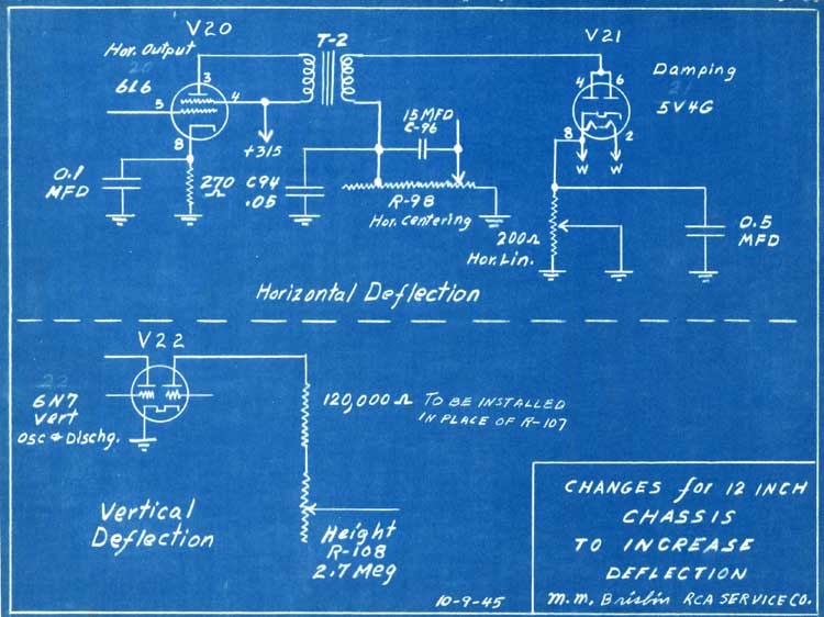
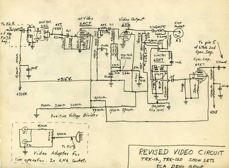
Dave Sica sent us these schematic diagrams of modifications to RCA TRK-12/120 sets for a demonstration of some sort. They are dated 1945.

The deflection circuit adds a bypass capacitor on the cathode of the horizontal output tube, and adds a horizontal  linearity control. It reduces the value of the series resistor in the plate of the vertical output tube. These changes would increase the sweep energy, which would be required with a higher anode voltage.

The video circuit modification is more extensive. The small diagram at the lower left is to feed the set with a video input. The main schematic is completely different from the original TRK-12. It uses two tubes as video amps, and changes the sync separator design. There is no AGC, and the contrast control adjusts the bias voltage on the IF stages. 

The video modifications are probably to get more voltage swing at the grid of the CRT. The 12AP4 data sheet says that the control grid needs 0-25 volts for "good contrast and brightness", and 0-50 volts for "maximum contrast and brightness".

Early Television

Early Television

Courtesy of Dave Sica


Early Television Museum
5396 Franklin St., Hilliard, OH 43026
(614) 771-0510
info@earlytelevision.org