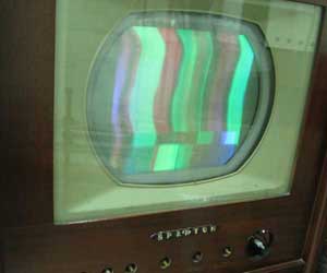
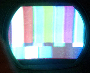
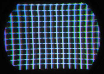
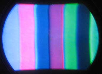
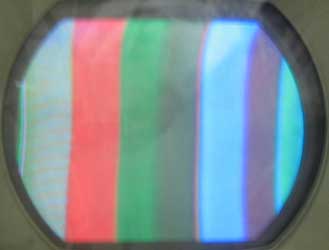
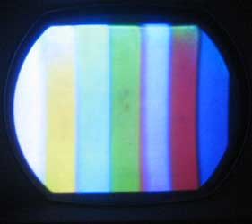
Early Color Television Sparton 16A211 RestorationSince the museum sold the CT-100 that we were using to display the 15GP22 CRT that was rebuilt by RACS, we have needed a working set using that tube. As a result, we decided to restore our Sparton. The previous owner had replaced most of the capacitors, but didn't complete the restoration. There were many parts with leads hanging. September 6, 2011 This made our work easy. I found where each loose wire went and reconnected the part. When I applied power and worked my way through the circuits, I found that most everything was working. However, color sync was very touchy, as was the horizontal hold. There was an arcing sound from the high voltage cage, which turned out to be a wire cut from the 20 kv line to the convergence pot. Fixing this also cured the color sync and horizontal hold problem somehow. I did notice excessive hum in the video, and replaced two electrolytics in the B+ and B- lines. Working with the set on the bench I don't have a CRT connected, so I couldn't actually see what the picture looked like. At this point I put the chassis back in the cabinet and connected the original CRT (a good 15GP22). As you can see in the picture below, the picture is in color, though there is a problem with hum. I will next look at ripple in the power supply. I suspect that either one of the replacement electrolytics previously changed is bad, or there was a mistake made in installing the new capacitor. September 9, 2011 I discovered that the previous restorer had not replaced two 80 mfd electrolytics. New ones cured the hum problem, but now the width is insufficient. I will check the tubes and voltages in the horizontal sweep section. October 4, 2011 I checked all the components in the horizontal section, and swapped the yoke. No change. Today I tried changing the value of the screen grid resistor in the horizontal output section. The original resistor is 5K. I found that shorting the resistor resulted in maximum width and about 17 v cathode voltage. The width is about 1/4 inch short on each side, so further work is necessary. Also, I don't know why this change in screen voltage is needed, unless, as someone suggested, there is a problem with the flyback. October 20, 2011 I spent some time re-checking all components and connections in the horizontal sweep section, and can find nothing wrong. I also experimented with changing the cathode resistor value in the hor. output section, and found that the original 180 ohm resistor produces the most width. I then experimented with adding a capacitor from the plate to the cathode of the damper. This trick was often used by technicians to get additional width. The problem is that high voltage usually goes down when you increase width in this way. I have very few high voltage small value capacitors, and I first tried about 40 pf. The width increased somewhat. The only other value I had was 1000 pf, which resulted in a picture that was overscanned by about 2 inches on each side. The good news is that the high voltage still remained above 20 kv. I have ordered some 100 pf 6 kv ceramic capacitors and will do further experimentation when they arrive, but I'm sure that I can find a value that will result in the proper width with plenty of high voltage. I've installed the 15GP22 that was rebuilt by RACS, and rewired the R, G and B control grid and screen grid connections. When RACS rebuilt the tube they didn't have any way to know how to orient the the electron gun, and installed it 120 degrees off. Today I will bolt down the yoke, put the convergence assembly on the CRT, and do a purity and convergence setup. I'll post the pictures soon. October 21, 2011 I did a quick purity and static convergence job, with good results. I found a 500pf doorknob capacitor which reads 400 on my checker and installed it across the damper. Width is just about perfect, with plenty of high voltage. I did notice that the horizontal convergence control did nothing - could it have something to do with the width problem? I'll check it now that I have the chassis on the bench again trying to figure out the color problem. October 22, 2011 The 6 kv caps arrived and I determined that 400 pf resulted in the right width and high voltage. I found a glob of loose solder that was causing intermittent video and a bad 12AU7, which resulted in no red. Now I have all the colors, good width, but the colors are wrong. I need to do an alignment of the color section. October 27, 2011 I noticed that the waveforms at the CRT grids contained lots of noise and that the colors shifted when the fine tuning was changed. This indicated to me that the set needed the IF alignment checked. When I connected the sweep equipment I discovered that it was way off. I followed the alignment instructions in Sams, which resulted in a poor response, with the top and bottom of the IF band down by over 6 db. I was able to tweak the 7 or so inductors to get a very nice flat response, with the visual carrier frequency down by 6 db as the specs call for. It is interesting that this set has a 21 mHz IF. By 1954 I think that all sets used 41 mHz. After doing the alignment I had nice clean color waveforms, but they didn't correspond to what they should have been. I adjusted the color phase inductor and the waveforms were correct. I now have the right colors. I'll do a complete setup later this week. October 28, 2011 Today I left the set on for about an hour. Everything held up well except the color sync, which became unstable. I'll have to take a heat gun to that section and see what is causing it. November 3, 2011 I reassembled the set and did a better purity/convergence adjustment job. The convergence turned out pretty good, and the picture looks great, so I moved the set back in the Color TV section of the museum. It was cool in there, because we have programmable thermostats on the HVAC system. When I fired up the set, the horizontal hold control was out of range. I waited a while, and as the set warmed up, the picture stabilized, but then a half hour later the hold control was out of range on the other end. Obviously I have something that is temperature sensitive in that circuit. That is also what is responsible for the color sync instability. I need to take the chassis out again and figure out what is going on. November 4, 2011 Found 2 resitors in the horizonal oscillator that changed value significantly when heat was applied. Changed them, and now the horizontal frequency is stable. Color sync is very touchy. At some time in the past a flexible drive was added to an inductor in the sync circuit, and a hole was drilled in the side of the cabinet to adjust the inductor. I removed it because I think the sync is stable enough now without the need to tweak the inductor. November 9, 2011 After turning the set on several times and watching it warm up, I determined that the color sync needed work. First I checked every component in the color sync circuit for heat sensitivity, and found no problems. Every part was within tolerance, too. The manual for this set mentions problems with color sync:
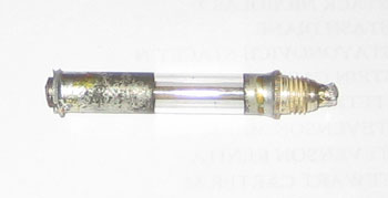
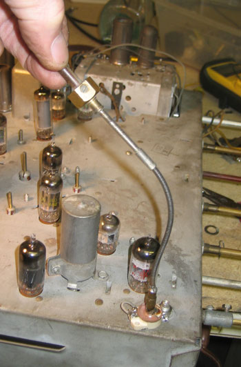
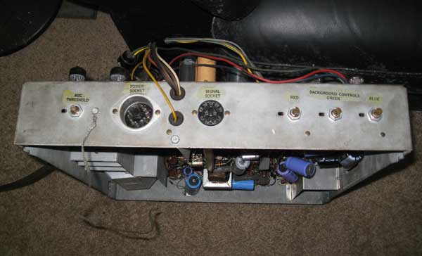
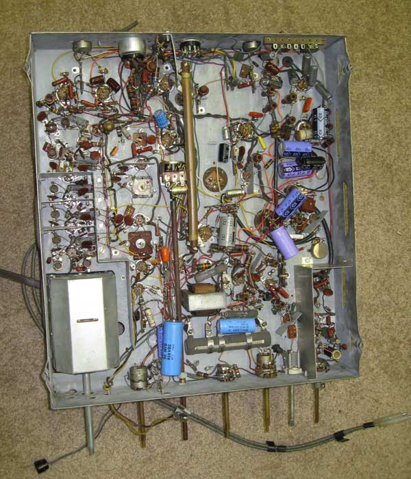
At some time in the past a flexible shaft was added to a trimmer capacitor and brought out through a hole in the side of the cabinet to help locking in the color. I decided to re-install the shaft. Unfortunately, the shaft had broken off from the trimmer in a way that it couldn't be repaired (see photos below). I used a different style of trimmer and soldered the shaft to it. I can now lock in the color more easily.
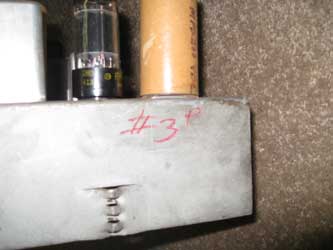
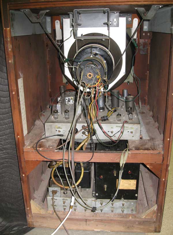
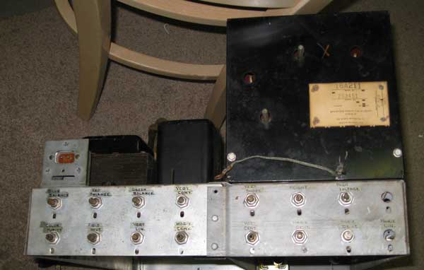
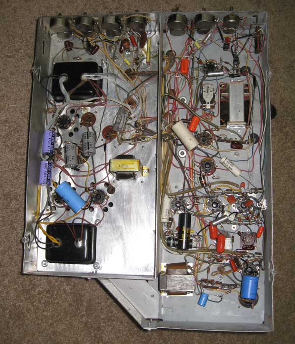
Back of the set, showing the CRT and two chassis
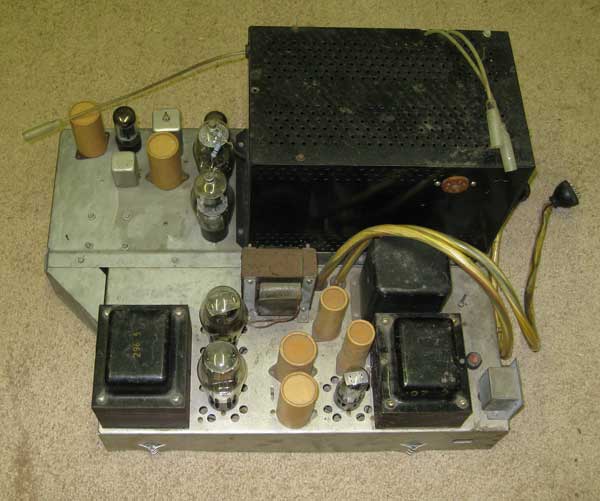
Power Supply/ Sweep chassis
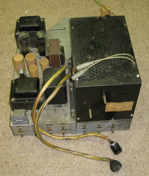
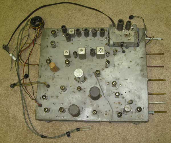
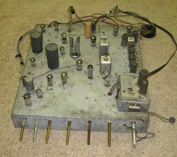
Video/Audio Chassis |


