Postwar Television
Diamond Power Image Dissector Camera RestorationThe camera has its own count-down sync generator, with both video and RF output.
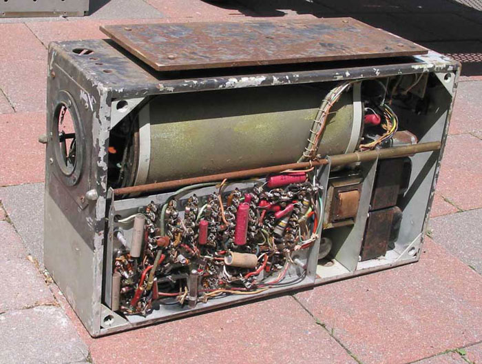
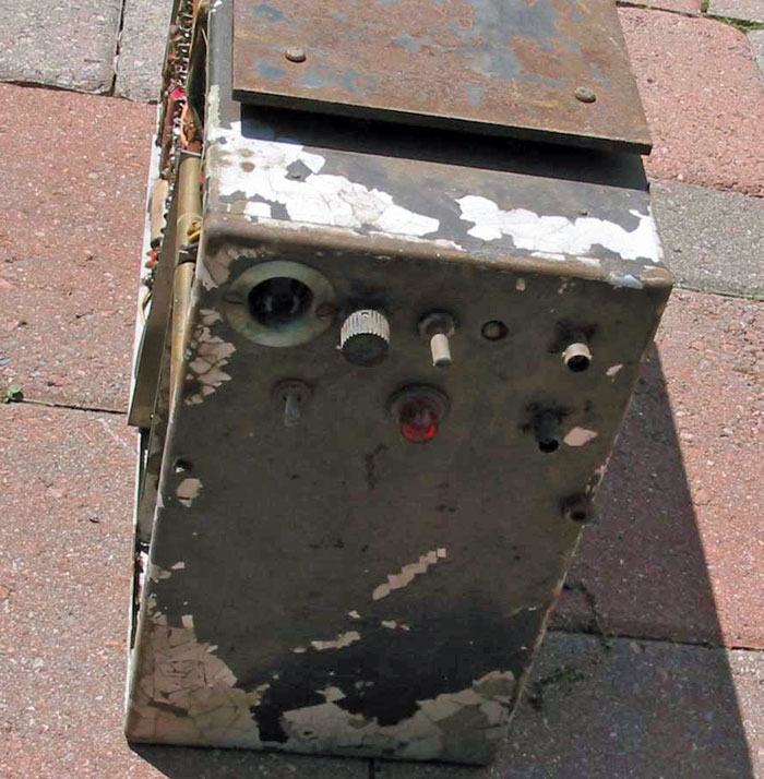
Side view. The dissector assembly is at the top. Below left is the Sweep Chassia. To the right is the power supply.
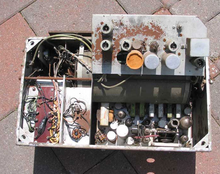
The other side, with the Video Chassis flipped up, revealing the dissector tube assembly and the Sweep Chassis.
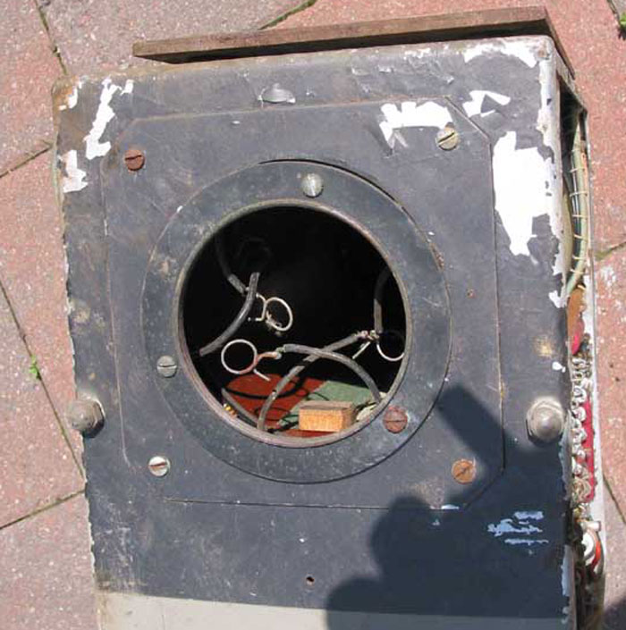
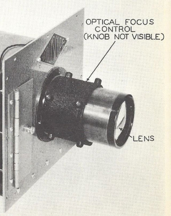
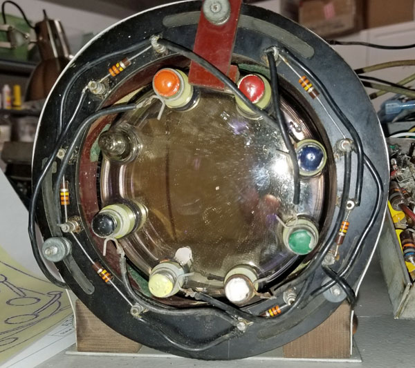
Front view, showing the lens mount and clips to attach to the dissector
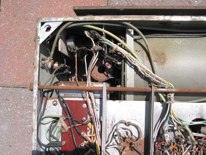
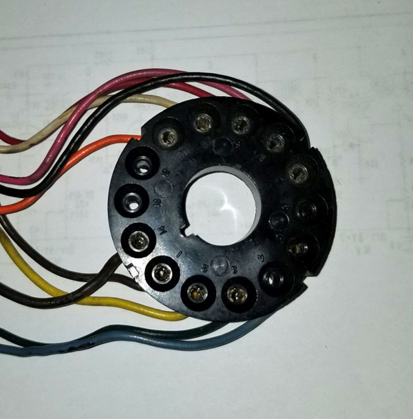
A view of the dissector socket
Rear of the camera, with ouput connectors and power input. Restoration ProgressNovember 24, 2018: We have taken the components out of the case. They all come out together, so there is no need to cut any connections. The case will be taken to an auto painter to refinish it. There is rust on the chassis, which we will attempt to remove. Our plan is to first document the schematic, which should be easy. We have a very complete manual on the model 300, which uses the same dissector tube, and includes setup and operating instructions. The circuits in the camera are:
Then, we will replace the paper and electrolytic capacitors, and fire it up. We have two dissector tubes - we hope at least one is good. We also have to locate a lens for the camera. December 1, 2018: I've made progress on documenting the camera. I have the schematic traced for the Main Chassis, which includes the dissector tube and the B+/Filament power supplies. The most thing I discovered is that there are two Sola constant voltage transformers in parallel. I also traced the schematic for the Video Chassis. I don't completely understand the purpose of all the diodes in the video amplifier, but it may become clear when I power it up. There is also a RF oscillator and modulator, using a 6U8. The Sweep Chassis uses a 12BH7, which was introduced in 1950. That dates the camera to 1950 or later. There is a more modern 6L6 on the Sweep Chassis. These tubes were made in the late 50s, so the camera was in use then. December 6, 2018: I've finished tracing the schematic of the camera. I'm sure there are errors that will show up later, but it is mostly complete now. Video Chassis: V and H sync are inserted in the first stage. A delay line apparently delays the H sync and re-inserts it later in the schematic. I used CLR to remove the rust from the chassis. It is much better, but not perfect.
Sweep Chassis: The sync generator consists of a master oscillator, followed by 4 countdown stages. I can't figure out how this works, since the horizontal sweep connects directly to the master oscillator, and the vertical sweep connects directly to the last countdown stage, and I can't come up with any combination of divide by numbers that results in close to 262 (15,750 / 60). I discovered a clue. The earlier version of this camera, the model 300, uses a free-running horizontal oscillator, at 21,500 kHz. This would result in a 358 line non-interlaced picture. If this camera operated with a horizontal rate of 22,500, then the picture would consist of 375 lines, and countdown stages of 5, 5, 5, and 3 would produce 60 Hz vertical. However, the camera has an RF modulator, suggesting that it was used with a TV set, which, of course, wouldn't work with that horizontal scan rate. It might have been used with a special set, or a demodulator and monitor. There is a differentiator to supply a feedback voltage to the oscillator to lock the vertical to the power line, but the wire connecting it is missing, so I don't know where it controls the oscillator. Also on the chassis is vertical and horizontal sweep, and a HV power supply for the dissector. December 7: I finished tracing the remaining circuits, including the divider resistors for the dissector. Next on the list is restuffing electrolytics so I can power up the Sweep Chassis. I want to see what frequency the master oscillator is. Assuming that the pot that adjusts its frequency hasn't been changed since the camera was last operated, it could tell us the horizontal sweep frequency. December 10: I have added connectors on each of the leads between the four chassis so that each can be removed for service.
December 20: I have re-stuffed two of the 4 20/20/20/20 450v electrolytics - enough to get the sweep chassis going. I applied about 50 vac to the power supply and determined that nothing was shorted, so I then went to full AC. I then connected the filament and B+ leads to the sweep chassis. My plan is to read the master oscillator frequency, hoping that the adjustment pot was left as it was when the camera was last used. I have reasonable voltages on pins 6 and 7 of V402, but my scope hasn't arrived yet to check the oscillator's frequency. I also recapped the video board - only a few paper caps there. December 22: Still don't have my scope here. So, I decided to do some calculations to determine the likely frequencies of the master oscillator and the dividers. I determined the values of the capacitors in the timing circuits and calculated the RC time constant for each. Here are the results:
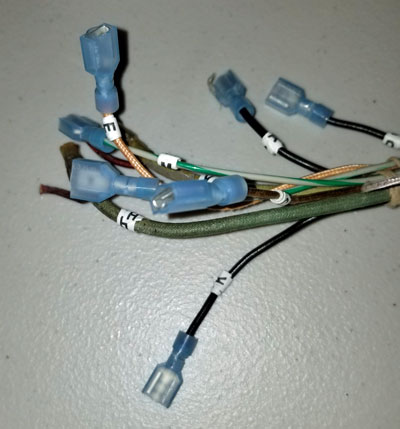
It appears that the dividers are 5, 3,10, 3, but the Master Osc. frequency doesn't appear to be practical for a horizonal scan frequency. Likewise, the last divider, which results in a frequency of 27 Hz, isn't likely as a vertical scan rate. Maybe the RC time constant calculation is wrong. It is based on a trigger at 63% of the discharge voltage. With a different %, all the calculations would be wrong. If our circuits trigger at 30% instead, the H and V scan rates would be 22,488 Hz and 60 Hz. This is in line with my early guess that the H scan rate was 22,500 Hz. There is a second option, dividers of 5, 6, 3 and 3. That would produce 60 Hertz for the vertical scan, and 16,200 Hz for the horizontal. 16,200 is close enough to 15,750 for TV sets of that time to lock in. The picture would have 270 scanning lines. December 28: I've finished restuffing the electroylics, and replacing most of the paper caps. I've held off on replacing those in the countdown stages in the hope that I can learn more about the dividing when I power up the chassis. I have ordered a bunch of 1N60 diodes to replace several that are bad. The model 300 has a 90mm F 1.4 lens, made by Miller Optical Co. Since the Image Dissector's target area is 2 inches wide, I need a lens designed for a medium format camera. I haven't found such a lens for sale yet, though I've found some that are similar. In addition to the lens, I'll need something to mount in it. I'll probably have to fabricate that.
Diamond 300 lens
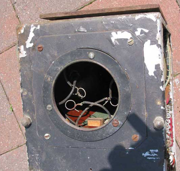
Lens mounting area. The diameter of the hole is 3 inches. January 3, 2019: Today I completed work on the oscillator and count-down stages on the sweep chassis. Here are are the frequencies of each stage:
Since the discriminator corrects the Master Osc. to produce 60 Hz at the output of the last countdown stage, we can assume that the Master Osc. is designed to work at 31.5 kHz. My first conclusion was that since it appears that the Master Osc. drives the horizontal sweep directly, the horizontal scan rate is 31.5 kHz, resulting in a 525 line picture. However, I decided to plug in the horizontal amplifier and output tubes and discovered that there is apparently a 15,750 Hz resonance in the output transformer, so the output stage locks on every other pulse. So the picture is 262 lines, with standard H and V sweep frequencies. I now understand how the horizontal sweep operates at 15,750 Hz. We have the manual for the model 300, which used a free running horizontal oscillator. The same circuit is used in our camera.
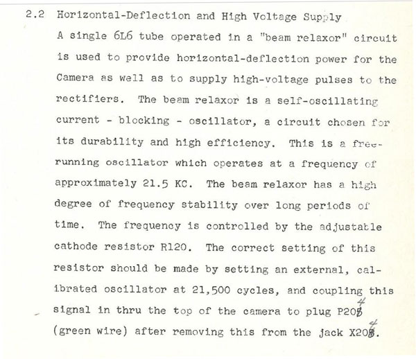
Model 300 horizontal Oscillator
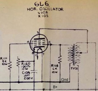
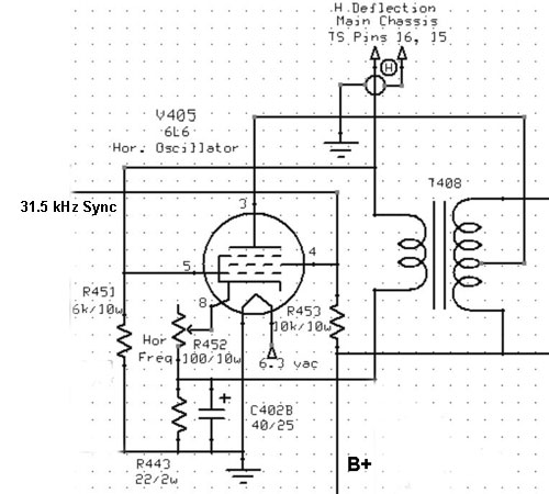
Model 300 circuit description In our camera the 31.5 mHz pulse from the master oscillator is amplified and fed to the screen grid of the 6L6. The 6L6 horizontal oscillator locks to every other pulse and produces a 15,750 scan rate.
Simplified horizontal oscillator in our camera January 5: I've completed restuffing the electrolytics. I've also finished installing connectors on all the cables from chassis to chassis.
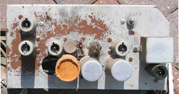
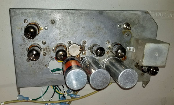
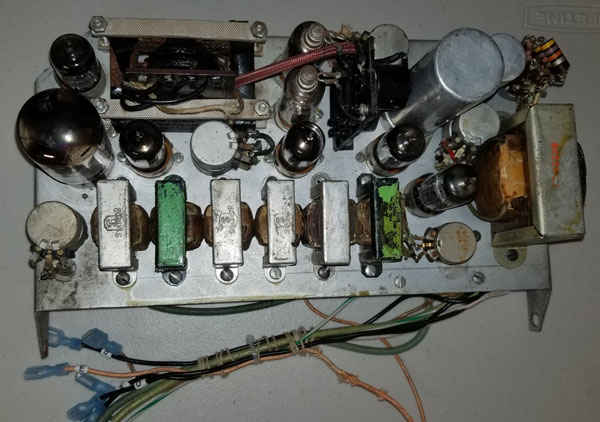
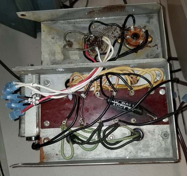
Completed Video Chassis
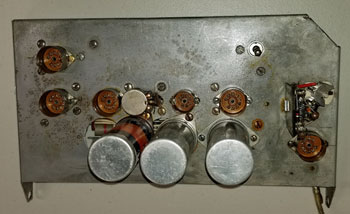
Completed Sweep Chassis
Completed Power Supply Chassis Next is replacing the capacitors on the main chassis.
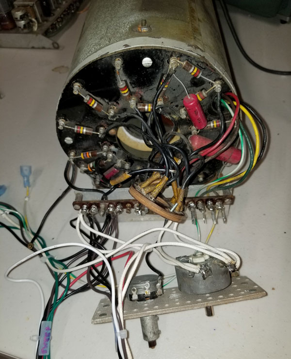
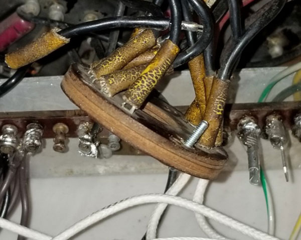
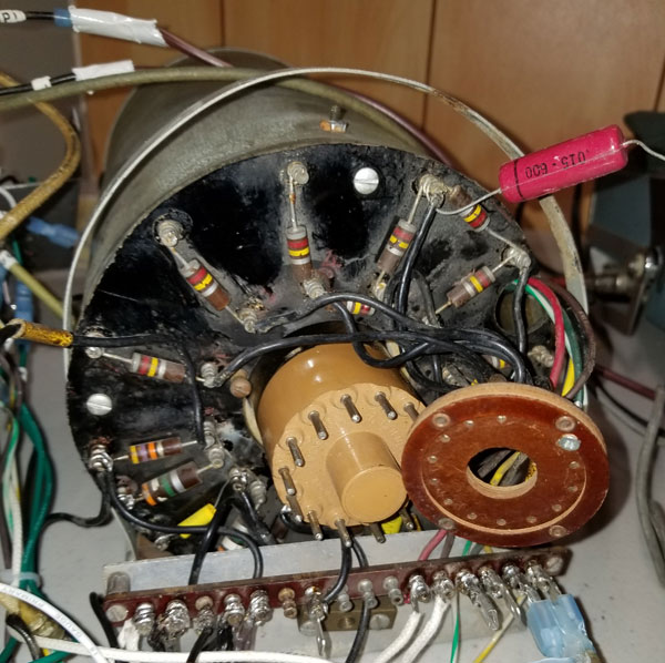
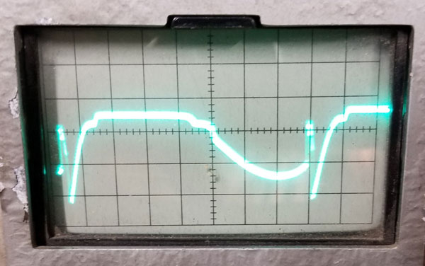
I also need to repair the socket for the dissector. Several pins have broken off. The best approach seems to be to drill a hole next to each broken pin and install a 2/56 bolt and nut, then solder the broken wire to it. January 11: I now have the master oscillator working at 31.5 Khz, the horizontal sweep at 15,750, and the vertical sweep at 60 Hz. The divider stages are working properly. I haven't yet checked the differentiator to see if it works. In looking at the waveform on the vertical deflection yoke I discovered that the WP-405 capacitor (C301, located on the Video Chassis), which is between the vertical output transformer and the yoke, is open. I can't find any data on this capacitor, but I'm sure it is a non-polarized capacitor. Because of the very low resistance of the vertical deflection yoke (1 ohm) the capacitor must be large. Darryl Hock suggested around 3000 mfd. The peak to peak voltage of the vertical waveform out of the vertical output stage is 6, so I have orderded some 1000 mfd/25 volt capacitors, three of which I can stuff in the original can. I then looked at the voltages in the dissector circuit. The schematic we have for the model 300 (a couple of years earlier than our camera) shows the HV is -2300 volts. The voltage in our camera measures -3200. Both cameras have identical power supplies (HV rectifiiers driven by the horizontal oscillator). There are 3 series resistors between the HV rectifiers, total of 560k, which connect to the voltage divider resistors that derive the voltages for the elements of the dissector tube. In the model 300, smaller divider resistors are used, totalling about 3 megohms. In our camera, the resistors total about 11 megohms. This explains why I measured -3200 volts at the beginning of the dividers, rather than the -2300 specified in the model 300 manual. From this I assume that the voltages I'm reading are normal, and that the designers decided that -3200 worked better with the dissector tube. I just unpacked the dissector tube and discovered that it has a different base than the one in our camera. It is a 14 pin base, like the ones on the 7JP4. 13 pins are used, like the base on the original tube, but I have no idea if the pin connections are the same. Also, there are 6 connections on the front of the tube, compared to 5 on the original tube. Only 5 have connections, like the original. I will need to figure out how to determine the pin connections without damaging the tube.
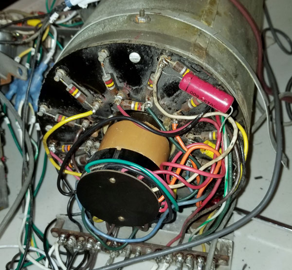
Rear view, showing original socket and end of dissector
January 12: I was able to identify the cathode and rings on the front and associate them with the connectors, so I know that part is right. I'll assume the pin connections on the base are the same (1-13) as on the original for now. The model 300 schematic shows -2300 v on the dissector, with 400 v between the cathode and ring 5. Our camera measures -3200 volts on the dissector and 1250 v between the cathode and ring 5. I noticed that R102 (3.9 meg) was cut. With it cut the voltage between the cathode and ring 5 is 860v. I think this camera uses a newer version dissector that worked with higher voltages. The tube I have is even newer, with the 14 pin base. To be safe, when I fire up the camera with the tube in it I'll reduce the HV to -2300 and see if I get video. I determined the polarity of the missing diodes in the differentiator circuit by trial and error. I connected a wire between V404 pin 3 (differentiator output) to the junction of R406 and C405, and the master oscillator now locks to the power line. However, I can't figure out how this works. There is no DC path from the discriminator to the master oscillator that would alter its frequency. The only connection is through C405, a 100 pf capacitor. Can anyone help me? January 14: After hours of experimentation I was unable to get stable locking of the master oscillator. Today George Lemaster sent me a magazine article about the Dage portable sync generator we have at the museum. It turns out that the sync generator schematic very similar to the one in our camera. Studying the Dage schematic I realized that there is no missing connection from the cathode of the discriminator (V404 pin 3) to the master oscillator. The plate of V404 (pin 1) actually varies the voltage on the line that feeds the pot (R404T) that controls the frequency of the master oscillator. It does that through R424. C414 provides a time constant for the voltage change. In our camera it was a 4 mfd. Since I thought its purpose was isolation, I replaced it with a 10 mfd, which I think is damping the correction voltage too much. In fact, I'm not sure the 4 mfd is correct - the Dage schematic has a .5 mfd capacitor. Now that I know how the circuit works, I can go back to experimenting with the polarity of D402 and 403 and get the master oscillator to lock reliably. January 16: Replacing C414 with a .5 (as is used in the Dage circuit) and reversing D402 and D403 allows the master oscillator to sync to the 60 Hz power line. It is relatively stable, but I think I can do better. Maybe germanium diodes for D402, 403 or 405 will help. They should arrive soon. January 18: I went back to the original Diamond circuit. I'm making progress. One of the diodes in the bridge was installed the wrong way. After changing that, the waveform out of the bridge is completely different.
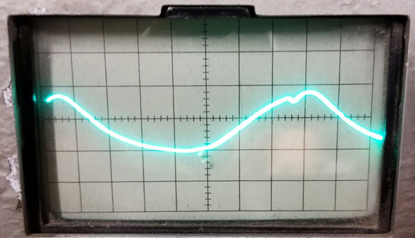
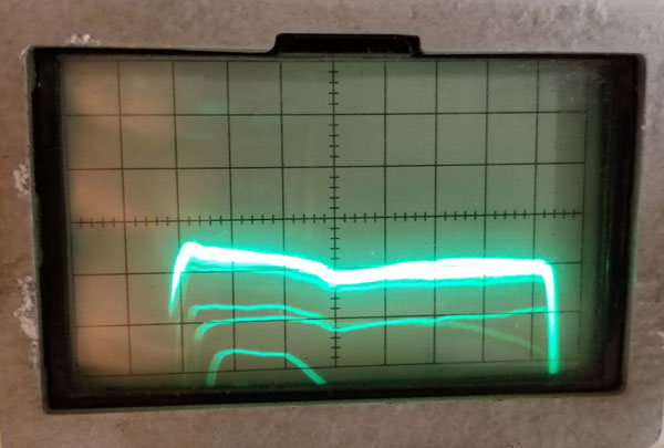
Output of bridge, showing pulse locked I spent a lot of time trying to get the dividers to be stable. I don't understand why both Diamond and Dage connected the line that provides DC to all the pots in the dividers to the plate of V404, other than to save a couple of parts. That line needs to be at about 80 vdc for the dividers to work properly. Connecting it to the plate of V404 provides that voltage, but serves no other purpose that I can see and there seems to be interaction between the master oscillator and the dividers. I disconnected the line and installed a voltage divider (R459 and R460) from the junction of R424 and R425 (there is about 160 vdc there) to obtain a stable 80 v for the line. Only the pot in the master oscillator is now connected to the plate of V404. The circuit locks reliably now, but there is some jitter. The second photo is of the plate of V404. You can see the pulse, but it is damped by the .5 capacitor.
Plate of V404 I will now move on to the dissector socket. I have a socket from a 7 inch electrostatic set, but it is missing some pins. I need 13 for the dissector. I'll take some from an octal tube socket. January 19: Here is the 7JP4 socket:
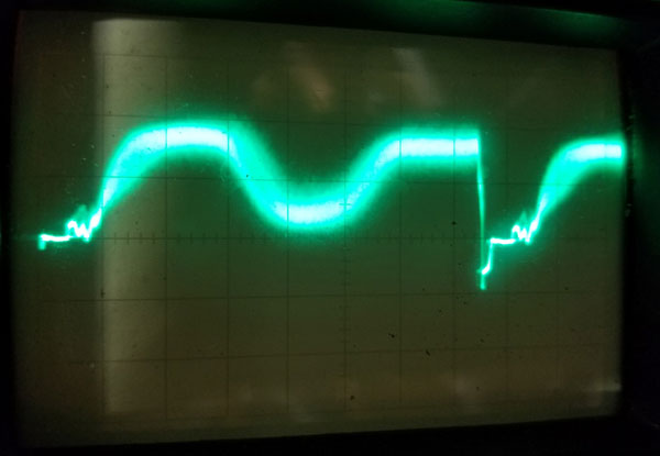
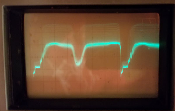
The socket on the dissector The non-polarized electrolytics to replace C301 have arrived. Next I need to double check the dissector socket wiring and make sure the sweep waveforms at the yoke are right. Then I'll be ready to see if the tube responds to light. I installed the dissector and powered up the camera. The tube is sensitive to light, which is promising. This afternoon I got the first waveform that shows that the dissector is producing an image. I covered the left half of the face of the dissector and shined a light into the tube. Here is the waveform:
Next is to work my way through the Video Chassis. January 20: Because I am working on the camera without its case, I needed to install a temporary lens mount. I found a plumbing drain at Home Depot that was just the right size to fit over the yoke assembly, and the lens I have (90 mm F2.8 slide projector lens) fit perfectly in the drain pipe end. The output of the dissector goes into V301 (refer to the Video Chassis schematic - link above) pin 2 (connector N). Horizontal sync pulses derived from the yoke (connertor L) and vertical sync pulses from the Sweep Chassis (connector F) are fed into the dissector through D301 and connector N for blanking. The sync pulses also go to V302 to be amplified. Looking at the waveforms at V301 pins 1 and 7 I had about a 20 v. negative going sync pulses, on top of about 1 volt of video signal. This swamped the cathode follower part of V301, resulting in no video at pin 8. I puzzled over this for a long time, and reported my results to some people who have been helping me with this project. Mark Nelson noticed that the output of V302 (the sync amp) was connected to the cathode (pin 3) of V301. Since the first half of V302 inverts the sync pulses, they would be out of phase with the sync pulses present at the input of V301 (pin 2). He surmised that the purpose was to cancel the sync pulses coming out of V301 (pin 1). I think he is right, and that the circuit isn't working right. If the sync pulses were canceled, only the video would be present at V301 pin 1 and the cathode follower would work properly. I will follow this idea to see if it solves the probem. January 26: Because of my lack of progress on getting the camera to work, I've gone back to the beginning. The 300 manual says that the dissector's output goes negative in proportion to the light on its surface. I have verified that with a test pattern. So, its output is the opposite of what is needed for a composite video signal. V301A inverts the video (white = 100%), V301B is a cathode follower so it doesn't invert it (white = 100%. V303A should invert it again, if I understand how the gamma corrector works (white = 0%). V303B inverts (white = 100%) and V304 inverts again (white =0%). V305 is a cathode follower, so no inversion (white = 0%), the opposite of what we need for a composite signal. Cliff Benham suggested that the camera had a non-standard video output. That seems strange, but Diamond sold companion monitors. We have two of them at the museum. When I get back to Ohio I will check them. His thesis is supported by the RF oscillator-modulator. One half of V305 amplifies (inverts) the video signal and feeds it to the triode section of V306, a cathode follower (no inversion), which, in turn, feeds the grid of the pentode section. This should modulate the RF with white = 100%. I will get that section working and test the hypothesis. I am sure that V302 is a sync amplifier, since D302 and D302 limit the input to the tube to eliminate the video portion. I measured the delay line, and it is 1.5 microseconds, just right to position the horizontal sync pulse. January 27: George Lemaster pointed out that my analysis of the RF modulator was wrong. Sync tips are 100%, while white peaks are 0%. That means that the video output and RF output are the same polarity. So the mystery of why both the sync and video polarity appear to be wrong remains. January 29: Some progress today. I went back to the beginning. First, I determined that the negative going H pulse coming in to the video chassis is to set the black level of the dissector. George Lemaster sent me an article by Howard Fink that describes how the dissector works. I verified that this was the case by disconnecting the H pulse and seeing that the dissector output went to garbage. I previously thought that the pulse was for blanking, but the waveforms for the model 300 show positive going pulses for blanking. Apparently our camera doesn't insert blanking into the dissector. I then disconnected the video input from the dissector so I could trace the sync path. The sync is stripped in V302. The width of the H pulse is that of the blanking interval. It is inserted into the video amp at the cathode of V301. The H pulse also goes into a 1.5 microsecond delay line and is inserted into the cathode of V304. At this point the H pulse that is inserted into the video is negative going, while the pulse after the delay line is positive going. It therefore subtracts from the negative going pulse, creating a pulse of 1.5 microseconds for sync and leaving a "back porch" the width of the blanking inverval. And, the polarity is correct and the sync/blanking out of V305 cathode follower is .4 v in amplitude, just right.
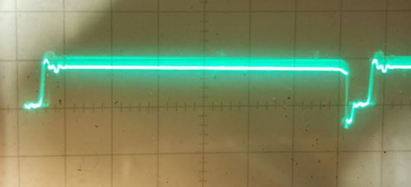
The horizontal sync pulse
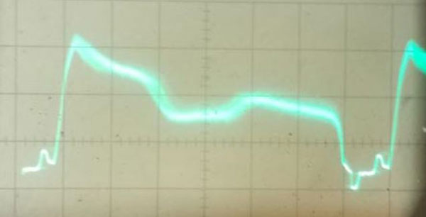
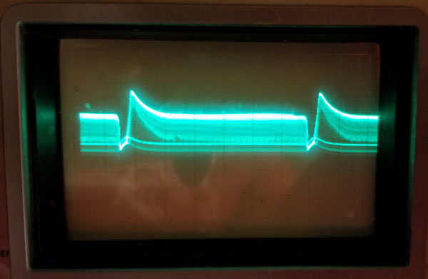
The composite waveform. The video is inverted - the camera is aimed at a black background with a white horizontal stripe on it. I have made no attempt to focus it. Now, the final mystery. Why is the video inverted? I have a theory, though it is far fetched. Maybe the camera was designed that way. It was used in power plant boilers, aimed at a thermometer in some of the photos we have. Maybe inverted video worked better to read the thermometer? Another possibility is that there are two types of dissector tubes, one with positive video output and one with negative. It is clear that the one used in the model 300, and our tube, produce negative video. Here is a description by Donald Fink of a dissector that looks like ours. Does it imply positive video output? January 30: I see only two possibilities here. Everything we have that describes the operation of the Diamond dissector suggests that its output voltage goes negative with higher light levels. The video amplifier stages create an inverted video output with that input. Diamond designed the camera for inverted video because that worked better for looking inside a boiler. The other, much less likely explanation, is that the monitors for the camera are designed for an inverted video input, and produce a standard video output. This is unlikely because the camera has an RF output, almost certainly for use with standard TV sets. We have two Diamond monitors in Ohio. When I get back I'll check that possibility. George Lemaster found a 1958 patent that describes the Diamond dissector. In reading the patent I see that no pulses are inserted at the dissector collector. In the model 300, blanking pulses (about 2 v pp, positive going) are inserted. In our camera, negative going H pulses (about 6 v pp) are inserted. The Fink article says that returning the collector to ground potential during retrace establishes a black level. When I remove the H pulse in our camera, the video becomes very noisy, so I assumed that the purpose of the H pulse was to establish the black level and are needed for proper operation. I discovered that I can remove the H pulse from the dissector and connect it only to D301 for the sync amplifier. Putting a 1k resistor from pin 2 of V301 to ground results in a good video waveform at the output of the camera. However, I have been ignoring the garmma corrector, which passes no video. I've essentially bypassed the diodes in order to get a video output. I checked all the resistors and the 3 diodes - they are all good, but no output. So, I changed the 12AU7 for a 12AT7, and the gamma corrector appears to work. However, the video signal overloads it. The only way I can get it to deliver a good video waveform is to reduce the input to V301 by a factor of 10 by changing the dissector shunt resistor from 1k to 100 ohms. When I do that, I get the below waveform, and the gamma correction pot changes the waveform, so I suspect that it is working. However, it doesn't seem right that the load resistor is that low.
Output waveform, with the gamma corrector working I then started looking at the dissector voltages, and in the process discovered that the focus pot is open. I've ordered a new one. I also have a monitor coming so I can see the image on a screen. February 7: The focus pot arrived, and I installed it. I discovered that though the above waveform looks decent, there is no V sync. After spending hours trying to understand how the camera is supposed to work, I've put that aside and have decided to experiment with how to make it work. The last modification I made (removing H pulses from the dissector collector and V301 and feeding them only to V302) resulted in a decent video and H sync waveform, but no V sync. Today I added a resistor from the V pulse to the input of V301 to insert a V sync pulse. It works relatively well. The video output is about 1 v pp, but my monitor has a 75 ohm termination, which drops the voltage down to about .4 v pp, not enough for the monitor to sync. I have ordered a video amp with adjustable gain, which should be here soon. Then, maybe, I can see a picture on the screen.
Line rate
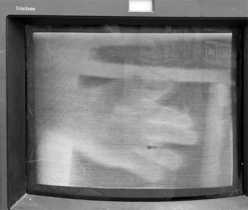
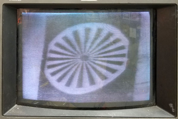
Field rate. The vertical sync pulse is not ideal, but should work. March 12: Unpacked the camera and connected it to a monitor. After messing with the electrical focus and size controls I finally got a crude image:
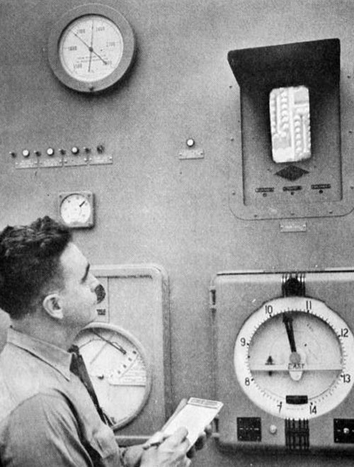
As we knew, the image is negative. probably because in certain conditions a negative image is more visible. Take a look at the photo below, of a Diamond Power camera in use in a power plant to monitor boiler temperature. Could that image be negative?
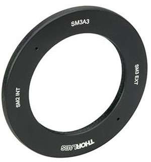
Focus is decent, but the image is noisy, probably because my lighting is inadequate. The main remaining problem is the parallelogram appearance. I'll explore this later. March 17: I traced a partial schematic for the Diamond Power monitor we have and discovered that it is designed to produce a negative image with a standard video input. This confirms that Diamond used negative images in their systems. I got steel cut to the proper size for the missing side panels, and took the case to a powder coat paint shop. It should be ready in about a week. I also ordered an adaptor ring that I think will work to mount our f2 90 mm lens.
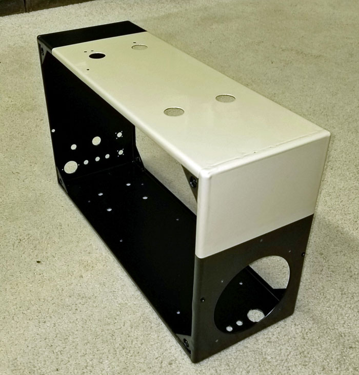
I took another look at the input to the video amplifier in an attempt to re-construct the original circuit. Using clues from the Diamond patent for their image dissector camera and from the documentation from the model 300, I arrived at a circuit that works and is probably similar to the original circuit. Refer to the schematic of the Modified Video Chassis. First, I added R353, a 1000 ohm load resistor for the dissector. R305 (39k) was already present. It connects the H pulse to the grid of V301. I added R354 (27k) to insert the V pulse into the grid. I also added D309 (1N60) to clip the H and V pulses going into the grid. Finally, I added R355 (33k) from a B+ source to the grid to provide a small positive bias. This positions the video signal so that it is above the blanking level. R301 (12k) was already present, connecting the V pulse to the input of the blanking amplifier (V302). I added R356 (10k) to insert the H pulse into the input of the blanking amplifier. I now have reasonable H and V sync pulses, and the video is properly positioned for the gamma corrector to work. I suspect that these functions were implemented with fewer components in the original circuit, but I'm happy with how it is now working. March 18: George Lemaster has researched the water level gauges made and used by Diamond Power and has concluded that the image on the monitor in the picture in the March 12 posting (above) is negative. March 30: The adaptor ring (shown above) didn't fit, so I'll have to find another way to mount the lens. The case is back from the powder coat company. As usual, they did a great job:
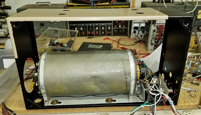
I have started putting it back together. The hardware has rust and corosion. so I'm soaking it in CLR for a couple of days to clean it up. Here is the case with the dissector assembly installed.
|


