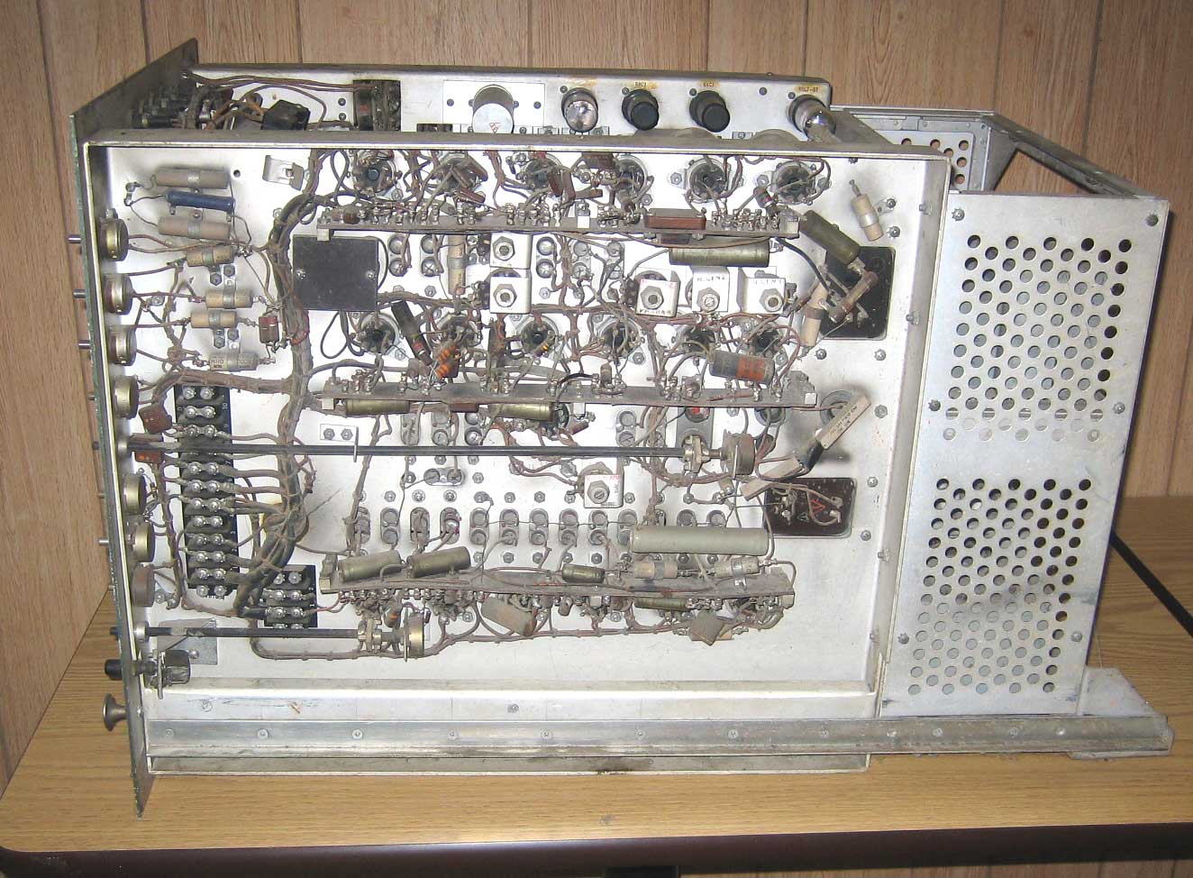
Javascript DHTML Drop Down Menu Powered by dhtml-menu-builder.com


What's New

Classifieds

Site Index

Resources

Contact Us


General Electric TM-5-A Studio Monitor

(Click on picture for a higher resolution image)

Click for technical information

This monitor was donated to the museum by Geoff Bourne. The following information is from George Lemaster:
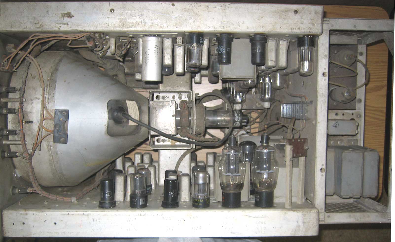
 

I have seen this monitor in your backroom at the last two ‘conventions’ and didn’t recognize it myself, and I’ve seen a lot of old broadcast gear. It is a 1949 General Electric TM-5-A studio monitor.

I now have a GE manual that I will donate to the museum that describes this monitor with schematic, parts list, alignment, etc. The manual is dated 10/49 and is for the GE 5 KW TV transmitter (with FM Phasitron exciter for aural). The separate ‘Transmitter Console’ manual dated 9/49 includes a Visual Test Monitor type TM-5-A. That’s it. The manual shows the front panel drawing of the GE TM 5A and this matches the photo on your website. GE wasn’t much for photos in the manuals like RCA, but GE does have detailed mechanical drawings.

The monitor was built in four models, one as a ‘master monitor’ and transmitter console, one for Cue Monitor Console, one for Line Monitor, and one for Camera Control. The main difference is that two of the models, the Line Monitor and the Camera Monitor versions have dual trace vertical and horizontal sweep for the scope. The manual I have does not cover the dual trace scope monitor version, it is the transmitter monitor version.

Isn’t it interesting that both RCA and GE had a CRT/scope monitor in the same era called TM-5.

The monitor manual schematic calls for a 10FP4 and 5CP1A scope tube. The HV supplies in the monitor are AC powered with 2X2A’s. It requires 110VAC plus 400V at 530 mA for the picture monitor, -105V bias at 10 ma, 300V at 350 mA for sweep and calibration circuit, and 400V at 170 mA for the amplifiers in the waveform chassis.  The -105 bias supply is in the manual and there’s a photo. The LV supply is dual with 3-6AS7’s for each the 300 and 400V supplies all on one chassis with 4-5R4GY’s.


Please Support the Museum