Early Color Television RCA CPA Prototype
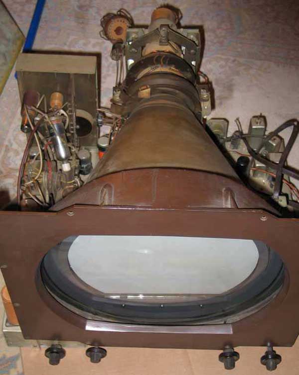
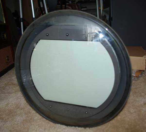
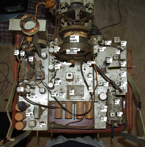
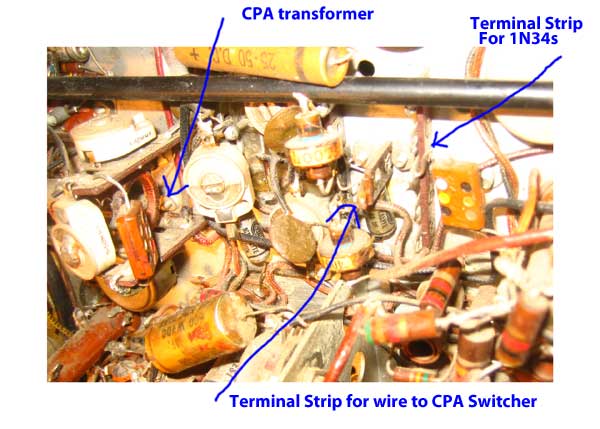
Recent History Several months ago this chassis was purchased by Harry Poster, a dealer in old television sets. He bought it from a picker in Pennsylvania, who knew nothing about its history. Harry offered the chassis to the museum, but we passed on it because of the asking price. Harry later put it on Ebay, where it was won by Nick Williams, a member of the television collecting community. Initial Impressions The chassis was obviously a prototype of some sort, predating the NTSC standard of 1953. It had some similarities to RCA prototypes from the early 50s, the Model 1-3 Field Test sets. The knob arrangement is identical to the Model 1 converter (designed to be attached to a black and white set to convert it to color) Model 1 Converter This chassis is not a converter, however, since it has a tuner. The tuner is a KRK-11, which was made in 1950. The chassis doesn't look like any of the photos we have of RCA Models 1-3. The CRT that came with the chassis is a RCA developmental tube C-73547, which is a higher number than the C-73293 in the museum's collection, which was made in 1950-51. Assuming the CRT in this chassis is original, the chassis is probably from 1952 or so, and may be a version of the Model 2 or 3. The CRT mounting arrangement on the picture of the model 2 is close to that of this chassis. Though RCA was the major player in development of compatible color, there were many other companies experimenting with color system. It wasn't clear who had made this chassis. Nick tested the CRT in a CT-100 and, amazingly, it is good. Research to Find Out What It Is Nick took high resolution pictures and posted them on VideoKarma. Color experts in the collecting community began to provide information to help identify the chassis. One of the important early discoveries that Nick made was a transformer, located near the reference oscillator, labeled CPA. CPA (color phase alternation) was an approach that RCA used beginning in late 1951.
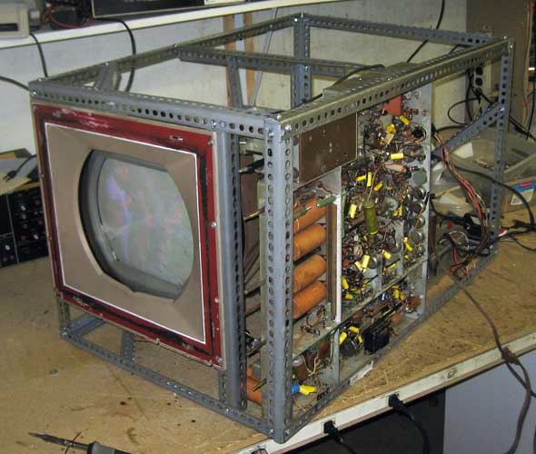
As Nick looked at the chassis, he could find no evidence that it was made for CPA other than the one transformer. Switching circuits were needed to alternate the phase of the signal from the CPA transformer, and no such circuits existed in the chassis. Nick then enlisted the help of his brother Tim to trace the schematic diagram of a good portion of the chassis. There was much speculation from the collecting community about what the chassis was, but the design remained a mystery. I then volunteered to clean up the schematic sketches, digitize them, and publish them so collectors could comment. The first thing I noticed was that the IF, sound, and video amplifier sections were almost identical to a 1952 RCA 21T176 (KCS-68C) black and white set, making me suspect the RCA was the manufacturer. In working with the diagrams I noticed that there were two tube sockets marked for 12AU7s near the reference oscillator with no connections other than the filiaments. I also noticed that the RCA and Hazeltine documents about CPA we had (see below for links to the patents and documents) used 12AU7s or 12AT7s for the function of CPA switching. I then began to explore the way in which the switching could have taken place. There were two approaches; one, used by Hazeltine, swiched the phase of the chroma signal out of the bandpass amplifier. The other, used by RCA, switched the phase of the reference oscillator. Since the two empty sockets on the chassis were very near the reference oscillator and a long way from the chroma bandpass amplifier, I concluded, after many emails with our color experts, that the switching was done at the reference oscillator. I then noticed that a RCA patent had a schematic diagram showing what looked like the CPA transformer, with a couple of diodes used to switch the phase into the red demodulator. The diagram was very similar, down to the values of the capacitors around the CPA transformer in the chassis. Then, I ran across another RCA patent that showed a color matrix/output design identical to the one in Nick's chassis. The was the final piece of information I needed to conclude that the set was made by RCA. The chassis was originally designed to test CPA. It originally had all the necessary switching circuits, but those circuits were removed when CPA was abandoned. The chassis was then rewired to make it work with some I/Q standard, perhaps the present NTSC standard. Because of the poor workmanship of the modifications, I suspect that it was not done by RCA engineers. Now that I have the chassis at the museum, I have been able to complete the documentation. I have also found where the switching diodes for CPA were located (see the photo below). What's Next? The chassis is missing several parts, including the crystal, power supply and the delay line. We don't know what frequency crystal was used, though we can use a grid dip meter to determine the present tuning of the oscillator. It would probably be possible to return the chassis to the original CPA design, though so far we haven't found any RCA circuits for the color field sensing circuits, though we have Hazeltine designs, which will be similar. The set could also be restored in its present configuration, or it could be left alone. Nick has decided that we will try to restore the set to the CPA configuration. I have built a power supply, and will attempt to get the chassis working. See the restoration page. A Wonderful Example of Cooperation Among Experts This research shows how a group of experts can collaborate to solve a complicated mystery. At each step along the way people offerered ideas, expertise and suggestions that eventually led us to an understanding of what this chassis is. Schematic Diagrams
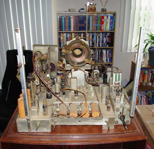
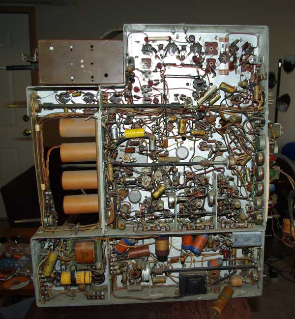
Documents relating to CPA Photos of the Chassis
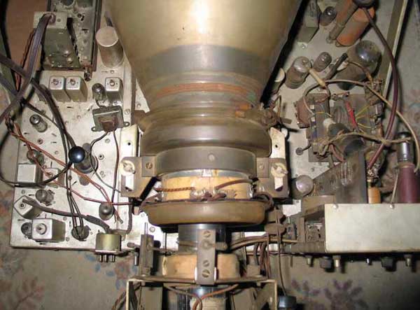
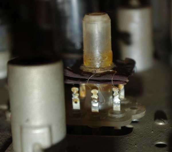
The CPA transformer
Photos courtesy of Harry Poster and Nick Williams
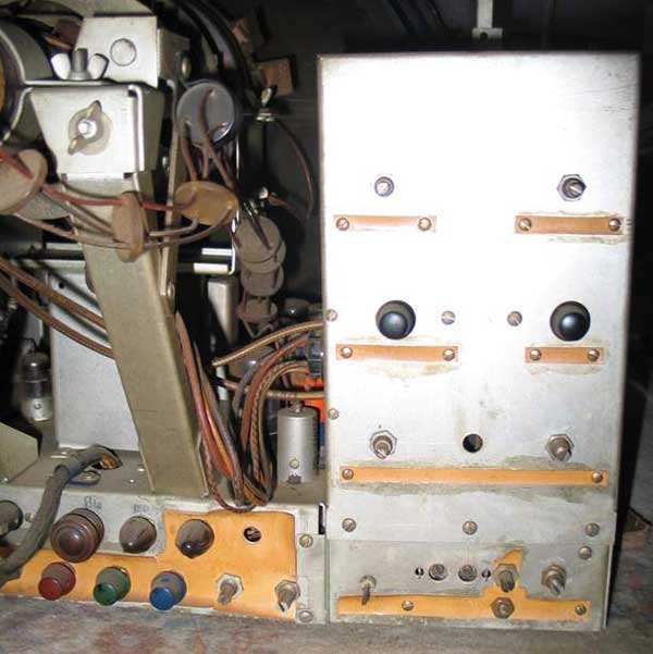
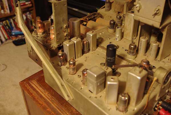
Location of terminal strips for CPA switching diodes
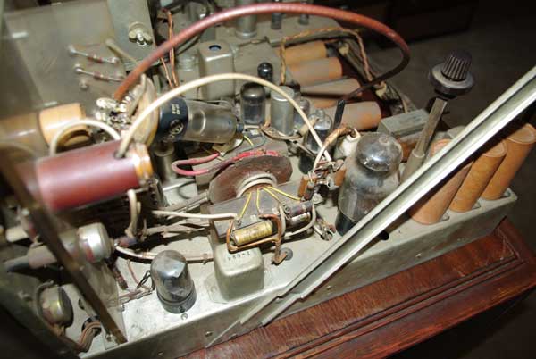
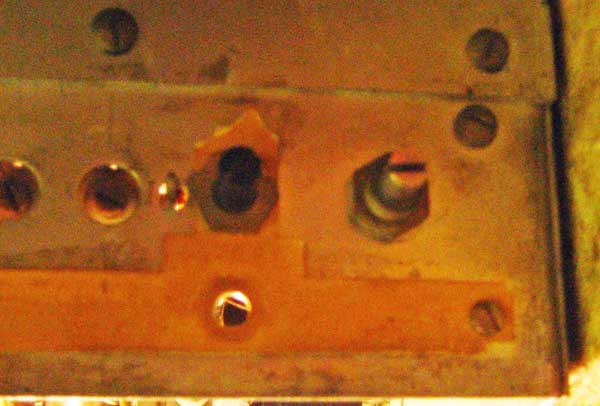
Location of horizontal convergence controls. Bottom hole is for an adjustible inductor, just above is the phase control
|