THE SETRestoration Log
CATCH-UP Last week sometime I worked out another "Here's where Sams is wrong." In my preparation for the keyed AGC restoration task, I found that the screen grid of the keyed AGC stage (V11 pin 7, 6AN8) does not go to 380 but to 375. The junction of R93/R95 (2R141/1R138 on RCA) also goes to 375, not 380 as the Sams schematic shows. This simplifies things since it eliminates the need for the 380 at this time, except as the source of 375, 285, and 275. I say 275 because maybe this is the time to power the already functional audio with THE SET's own power supply. It may also provide an important load to ensure correct division of the output from the main voltage-doubler power supply, which has a nominal 380-volt output.
8-1-99 To achieve my next milestone, an up-and-running keyed AGC and horizontal sync separator, it will be necessary to generate 375 and 285 volts from the main 380-volt voltage-doubler power supply. As is my practice, I preconditioned the isolated 375-volt bus with an external power supply by gradually, over a thirty-minute period, raising the bus to the full 375. In this instance, as reported earlier, the quiescent current was 25 mA. I next repeated an earlier test by connecting the variable power supply to the isolated voltage doubler (C2, C1, etc.) and monitoring the voltage drop across the series-aiding caps to ground. After 20 minutes of gradually increasing the voltage, at 380 volts there were only 5 mA of quiescent current drawn by the caps. 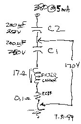 However, as expected, the voltage did not divide equally across the caps. There were approximately 210 volts across C2 with the remaining 170 across C1. These are 200-uF 250-volt caps, so C1 was not receiving a test of its full operational voltage, which I conclude should be at least 175 volts. So I boosted the power supply to 406 volts which put 181 volts across C1. The quiescent current was only 7 mA and falling.
My original plan was to use a variac at this point to slowly bring up the power supply. I couldn't find a variac. So it's improvise time. I jury-rigged the cheater cord I'd been using to power THE SET to put a three-speed hair dryer in series with the ac line. I switched the hair dryer to low (maximum resistance) and turned on the power. Low on the hair dryer put 70 volts rms on the primary of the power transformer. The dc output was 255/117. High on the hair dryer put 99 volts on the primary of the power transformer. The dc output was 362/172. So far, so good. 8-2-99 July was the hottest month on record for the area, and we had many power outages over the month. It was common for the voltage at my abode to run 108 and regularly dip lower. Today is another record breaker, but it's supposed to be the end of the heat wave. So, since running the main power supply directly from the ac line (sans hair dryer) is a goal, I measured the ac line. It was 115. Since, without heat waves, it usually runs five volts or more higher, I took advantage of the relatively low line and powered up the isolated main power supply while carefully monitoring the 380-volt bus. At 115 Vac, the dc on the 380-volt bus was 437 and the 175-volt bus ran 206. Everything seemed stable; there were no snaps, crackles, or pops. Neither C1 nor C2 had its voltage rating compromised, which may support my speculation that initial turn-on routinely drives the voltage-doubler supply way over nominal bus ratings. So far, still so good. 8-15-99 Today I spent a little time cleaning the front of the chassis -- the only area left with 45 years worth of fuzzy film build-up. I've recently been working on a method to gradually switch to the set's own power supply as more circuits are made functional. 8-26-99. On 8-17-99 I had ordered audio output transformer P-T291 from AES (Antique Electronic Supply, Tempe, Arizona) for $13.95. Yesterday, UPS delivered it and some other stuff for THE SET including a box of type 51 dial lamps, assorted axial-lead capacitors, and a 0.22 uF, 600-volt 'orange drop' for possible use in the flyback circuit. The audio output transformer (manufactured in 1999) replaces the missing unit that RCA mounted on an 8-inch loudspeaker that had been in the lower portion of the mahogany cabinet. I soldered the transformer to the three flying leads (plate, screen, and +275 volts) from the chassis, connected a 12-inch Electro-Voice 'Wolverine' speaker mounted in a floor-standing Electro-Voice model Marquis mahogany enclosure (bought it new in 1961), installed a Sylvania 6AQ5A audio power amplifier, connected the regulated power supply to the 275-volt bus, confirmed that tuner B+ was still strapped to +275, warmed up the filaments, connected the outdoor antenna, and cranked up the voltage. Although I did 'visually-hear' the audio with an oscilloscope last month, this is the first time in 33 years that the complete RF-into-sound chain functioned. The class-A audio power amplifier draws maybe half as much current as all the other stuff on the 275-volt bus -- current demand on the regulated supply went from about 100 to nearly 150 mA. Since the power supply is rated 125 mA intermittent, I ran the system at around 225 volts to hold current to the 125-mA rating. All is fine at the lower bus level, but I had to tweak the volume control to compensate for a drop in sonic level caused by the 225-volt bus. The sound is a bit mellow. Due more to the E-V speaker, I guess, than RCA's design. A real tone control (not the worthless treble-cut type) cuts the low end of the sound spectrum when fully clockwise. A quarter-turn counter-clockwise boosts the bass to where a rerun of 'Danny and the Juniors' on American Bandstand would rate a 10 for "...it's got a good beat." Beyond that, the treble begins to wane, but the boosted bass remains, resulting in earmush. [A friend in tech school had a part-time job at WFIL-TV where Dick Clark's American Bandstand originated live from downtown Philadelphia. He took me there for a tour (I remember how incredibly sharp the B&W studio-monitor video was and how small the actual bandstand set was), and I applied for, but didn't get, a similar after-school job. An ABC affiliate, WFIL was the first station in Philadelphia to originate live color shows. For some reason they scooped WRCV, the local NBC station. WFIL-TV had one RCA TK-41 color camera, which my buddy did get to operate, including during evening news programs. When they had to cut from a live news guy to a live color commercial, they would fade-to-black, he'd swing the 300-pound camera around and focus on the new set, and the control room would bring up the video. That's one job I wish I had added to my teen-aged resume. Soon thereafter though, I landed the WBUX job.] All's good!
|