is shown fitted into its 19.5 kV high-voltage connector.
There is only one pigtail lead on 50-megohm resistor R168/3R253; it is soldered to pin 1 of the 15-megohm user-adjusted convergence potentiometer [R24(SAMS) 3R254(RCA)], seen as a dark semicircle behind the resistor.
This circuit is a five-element series resistive voltage divider to ground. A second, horizontally mounted, 50-megohm high-voltage resistor [R185/3R255], seen in the upper right of the graphic, constitutes the third of the five elements. It connects between the second element, the convergence pot, and the fourth element, the high-voltage control [R25/3R256]. The final element in this five-leg series-resistance voltage divider, a 1.8 megohm resistor [R184/R3R257], connects to ground (final two elements not seen in this graphic). 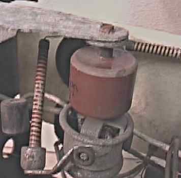 Graphic is a 2001 image of unrestored CTC-2 chassis B8002390.
Stacked to the right of the 50-megohm resistor is a 500 micro-micro farad high-voltage capacitor used to filter the 19.5 kV. A hex-head metal screw connects one end of the filter cap to ground (top of image). The other end is rivited to the 3A3 high-voltage rectifier cathode/filament corona ring, in which the octal socket for the 3A3 is nestled. The 3A3 is mounted upside-down in a CT-100. The same area of a restored CTC-2 high-voltage cage is shown below. Victoreen high-voltage resistors have replaced the original production components. A soldered pigtail lead now connects the new 50-megohm R168/3R253 directly to the cup. 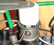 Graphic is a 2002 image of restored CTC-2 chassis B8000619.
|