
| The Set: Pete Deksnis's Site about the CT-100 Restoring a Vintage Color Television Set |
THE SET
Keyed AGC
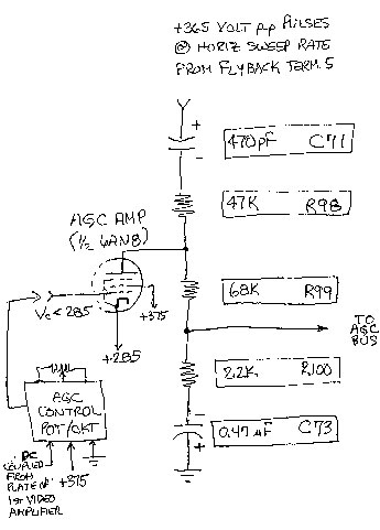
The essence of the keyed AGC circuit is shown in my hand sketch, which uses Sams reference designations. It is typical of AGC circuits utilized in the early fifties. It works in the CTC-2 chassis something like this...
PART 1.
As indicated on the sketch, voltage Vc on the control grid of the AGC AMP is lower (by 10 volts or so) than the +285 volts on the cathode. So, it's low enough to drive the tube into cutoff.
Fifteen thousand, seven hundred and fifty times each second (15,734.26 actually, but who's counting) a +365-volt pulse from a tap on the flyback transformer drives the AGC AMP plate positive. That's enough to overcome a cutoff condition and drive the tube into conduction for a few microseconds. But for most of the time, for maybe the next 50 microseconds or so before another pulse comes along, the tube ISN'T conducting.
Because 470-pF capacitor C71 is in the conduction path, it charges to a couple of volts with the polarity shown. Since a cut-off tube exhibits high impedance and there's no real fast discharge path, those few negative volts will appear on its plate whenever the AGC AMP is cutoff.
With the AGC AMP slamming in and out of conduction all the time, a relatively large cap, C73, is added to keep the negative dc at the "TO AGC BUS" line relatively smooth.
PART 2.
Our objective is a TV picture of consistent contrast and quality, even though RF levels of the received television transmission vary considerably. To accomplish the objective, the gain of the receiver must be varied as the strength of the RF signal from the TV transmitter varies. To control gain automatically, the keyed Automatic Gain Control circuit needs a reference. It must know what the received signal strength is.
Keyed AGC uses the amplitude of each horizontal sync pulse as an indication of signal strength. The same time a +365-volt pulse from the flyback whams the plate of the AGC AMP, a sample of the already-detected horizontal sync pulse is taken from the plate of the 1st video amplifier and applied to the control grid of the AGC AMP. If the sample is, say, MORE (or less) than the last sample, it will drive the grid of the AGC tube a bit MORE (or less) positive. That makes the tube conduct even MORE (or less). Which causes MORE (or less) charge to develop across C71. That in turn puts MORE (or less) negative charge across AGC filter capacitor C73.
[I won't know what the extents of the AGC levels are until the keyed AGC circuitry is in operation, but so far minus 1 to minus 10 volts applied to the AGC bus from a bias supply has been the value used to test THE SET.]
PART 3.
It's all a big closed loop.
An AGC voltage that becomes more negative lowers the gain of RF and IF stages, so the amplitude of horizontal sync pulses on the plate of the video amplifier will decrease.
[A] That means the AGC AMP will not conduct as hard, so the AGC voltage will become less negative, which increases the gain of RF and IF stages, so the amplitude of horizontal sync pulses on the plate of the video amplifier will increase.
[B] That means the AGC AMP will conduct harder, so the AGC voltage will become more negative, which decreases the gain of RF and IF stages, so the amplitude of horizontal sync pulses on the plate of the video amplifier will decrease.
[A] That means the AGC AMP... [love that copy-and-paste!] ...will not conduct as hard, so the AGC voltage will become less negative, which increases the gain of RF and IF stages, so the amplitude of horizontal sync pulses on the plate of the video amplifier will increase.
[B]That means the AGC AMP will conduct harder, so the AGC voltage will become more negative, which decreases the gain of RF and IF stages, so the amplitude of horizontal sync pulses on the plate of the video amplifier will decrease.
[A]That means the AGC AMP will not conduct as hard, so the AGC voltage will become less negative, which increases the gain of RF and IF stages, so the amplitude of horizontal sync pulses on the plate of the video amplifier will increase.
[B]That means the AGC AMP will conduct harder, so the AGC voltage will become more negative, which decreases the gain of RF and IF stages, so the amplitude of horizontal sync pulses on the plate of the video amplifier will decrease.
Which all tends to work in our favor and generally accomplishes the objective -- a picture of consistent contrast and quality.
Last Updated on 3-14-00.