
|
Vintage Television Sets and Colour Television Sets from the Dawn of Television until Now
Echard Etzold's Site |

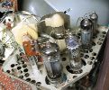
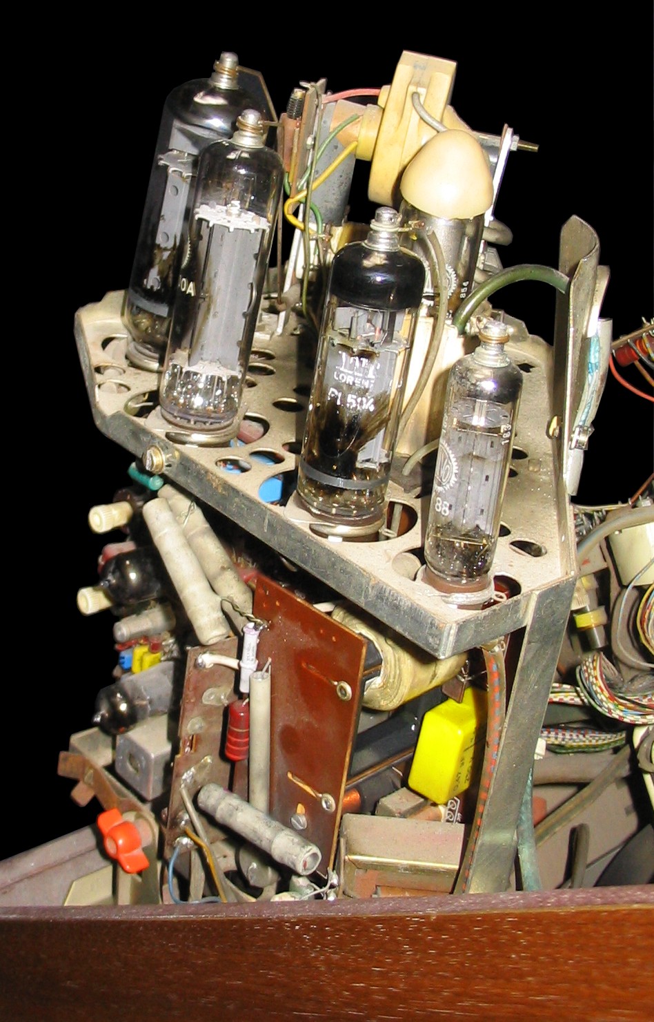
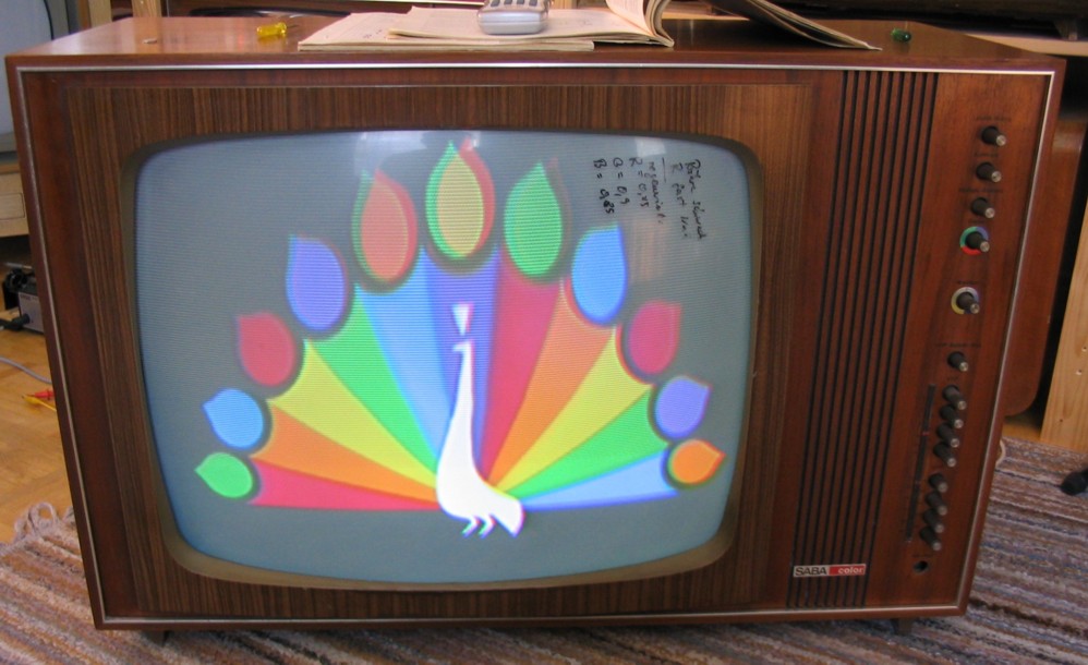
The SABA Schauinsland T 2000 color is a unique television set model in the first generation of colour television sets made in Germany. While the majority of brands favored transistor technology with only a few tubes, the SABA television set has 28 tubes total. This model is probably the largest chassis ever produced in Germany. The chassis is divided into three parts, the left chassis, the amplifier chassis and the deflection unit. All parts can be separately pulled out without difficulty. While all the other television brands (except Philips) tried to minimize the number of tubes, SABA decided the opposite. As SABA explained in the Service manual: "To make service and fixing easy for the serviceman who is stressed by the new colour television technology, the SABA Schauinsland T 2000 color was equipped predominantly with tubes. Tubes have the advantage that they are easily replaced and that the functions of this new schematic are easier understood than transistor circuits. Transistors (13 in total) were only used where they have functional and schematic advantages. Of course this results in higher power consumption. But because the major power consumption is in the deflection and high voltage units which are similar in every colour television set design, the difference with respect to a more transistorised television set is marginal and the differences can be balanced by improved air cooling."
|
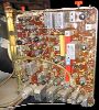
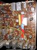
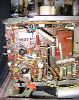
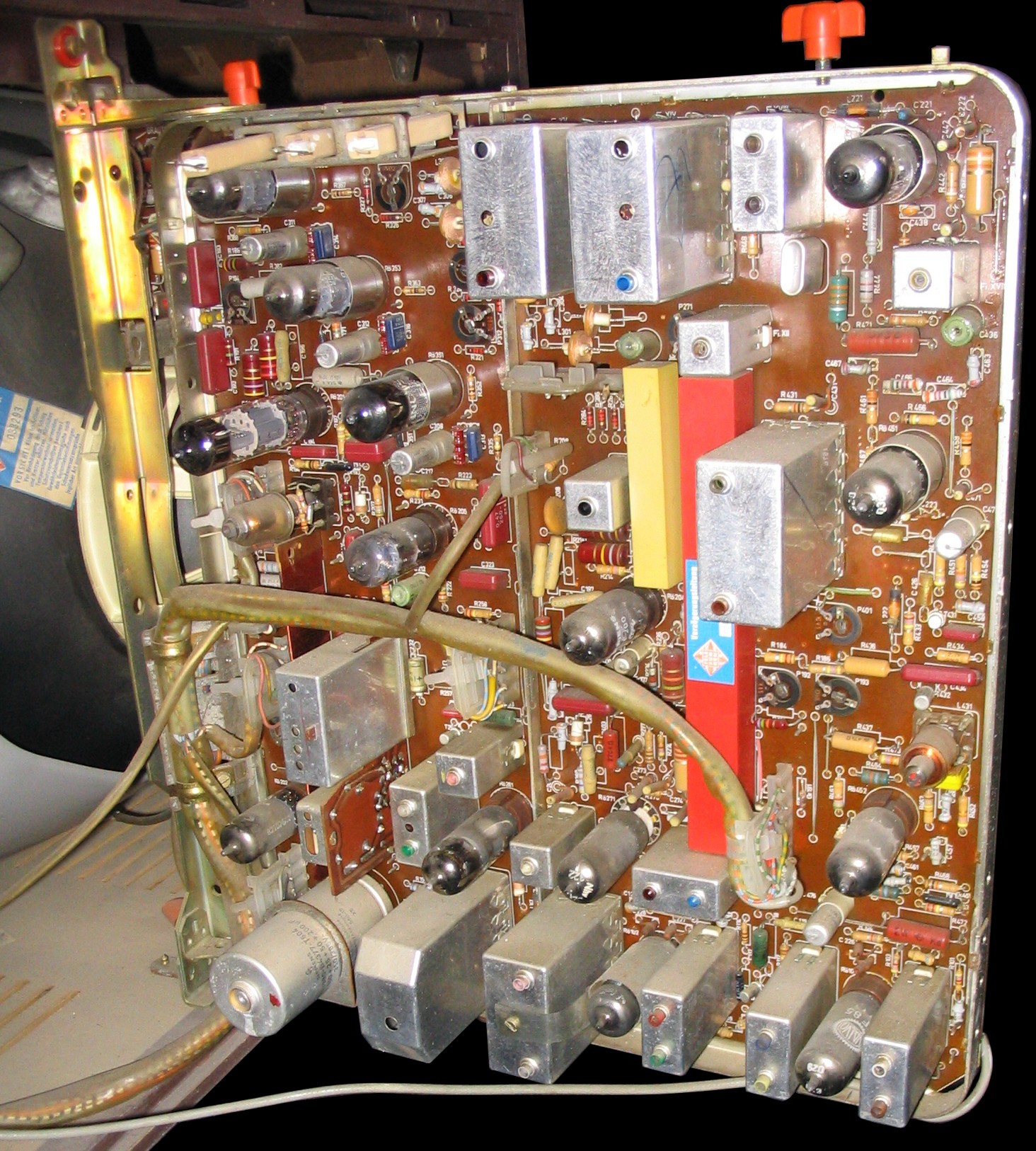
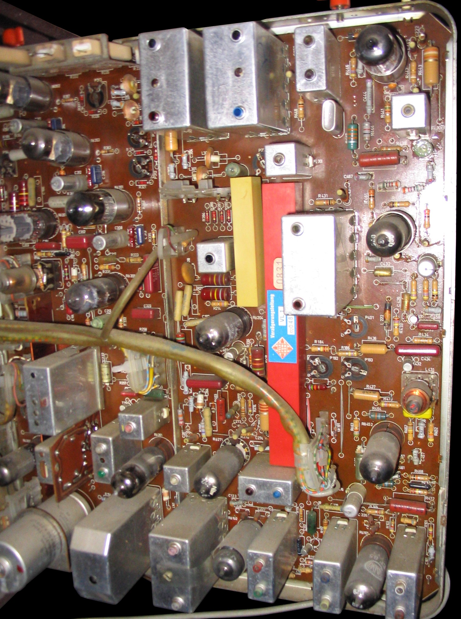
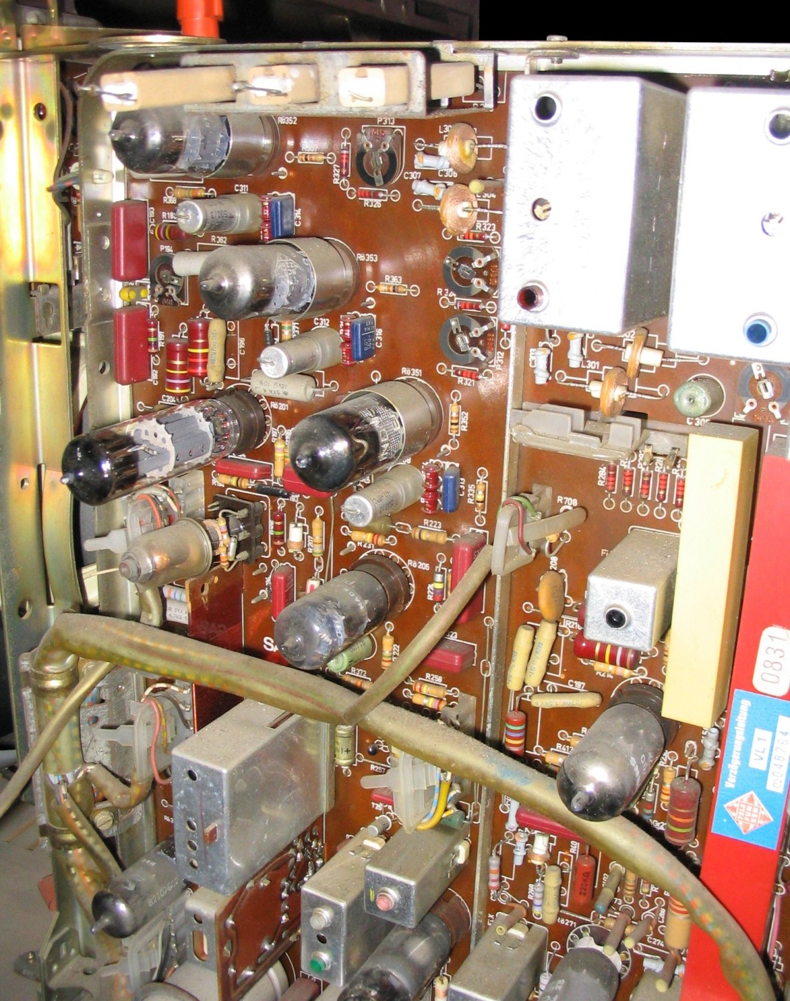
The amplifier chassis is a single board on the left wing, which can be tilted around the vertical axis. The amplifier chassis contain the IF amplifier, A.G.C., y or video amplifier with y delay line, sound IF amplifier, sync separation, chroma amplifier, PAL demodulator with the PAL delay line, synchron demodulators (i.e. the R-Y and B-Y demodulator of an NTSC television set, but modified for PAL with the PAL synchronisation switch), matrix, chroma difference amplifier, colour killer, burst amplifier, PAL identification, 4.43 MHz oscillator, and PAL switch with 7.8 KHz oscillator and blanker. Tuner, IF, and y amplifier are schematically identical to B/w sets. To improve the picture quality some more video amplifier units were inserted into the luminance amplifier section.
|
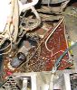
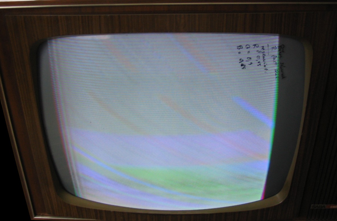
The picture tube is a delta shadow mask colour picture tube A63-11X, made by Telefunken. The CRT was very bad on all three guns. Red had no emission. With a picture tube rejuvenator, which measures the emission of every gun and calculates the rejuvenation current with a built-in computer circuit, the CRT could be activated again. After rejuvenation the emission for red and blue was 0.85 mA, the emission for green was 0.9 mA. These are very good values for a CRT of this type. It is unknown how long the improved emission will last.
|
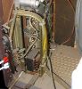
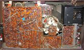
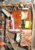
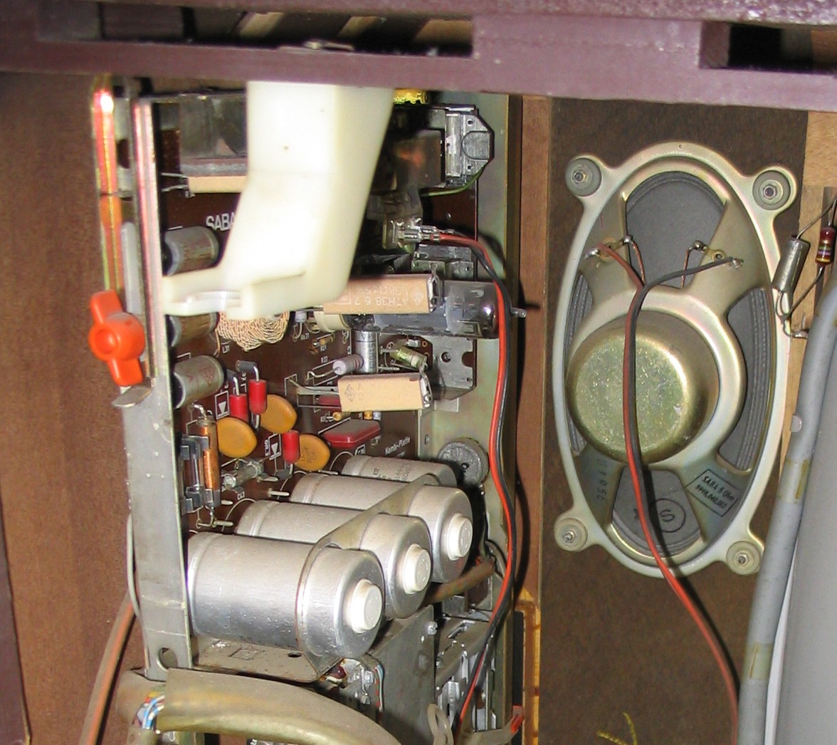
The chassis on the left wing contains the controls for contrast, loudness, brightness, colour, and channel selection. There are four buttons for four VHF programmes and four buttons for four UHF programmes. Beside them the chassis contains the power pack, sound amplifier, and the connections for antenna and an external loudspeaker. From the VHF tuner a coaxial wire is connected to the IF amplifier on the amplifier chassis. The total power consumption is 350 watts. The power pack provides 285 volts for the line output and high voltage unit.
|

In the early European colour television sets there are two different ways of generating the colour video signals for the picture tube: The RGB concept and the chroma difference concept.In this television set the chroma difference concept is realised.
In the chroma difference concept is one wide bandwidth luminance amplifier which is connected with the three color cathodes of the CRT together. The chroma difference signals U (R-Y), U (G-Y) and U (B-Y) are amplified in three small bandwidth amplifiers, which are connected with the three Wehnelt grids of the CRT. The red, green and blue signals are decoded in the CRT itself by calculating the difference signals. The chroma difference concept has the advantage that only one 5 MHz wide bandwidth amplifier is necessary instead of three in the RGB concept. The chroma difference amplifier needs only a 1.2 MHz bandwidth. The tubes for a chroma difference amplifier (EF184) are much cheaper than for the RGB concept and they need smaller currents. Another advantage is if there is a defect in the chroma channel the set will still provide a true b/w picture.
The purpose of the colour killer circuit is to disable the chroma channel for b/w broadcasts. If the chroma channel is open during b/w reception, parts of the video signal which lie in the range of the chroma signal will reach the chroma demodulators and cause colour bars and colour noise in the b/w picture. In case of a low antenna signal the killer disables the chroma amplifier too, because coloured snow will reduce the joy of watching a colour television broadcast. A b/w picture is better to watch than a colour-noised colour picture. The killer is the triode of the PCL84. The triode functions as a regulated rectifier and rectifies the positive flyback pulses (560 Vpp), capacitor coupled to the anode. The negative D.C. voltage is filtered and is applied to the grid of the chroma amplifier output tube, effectively placing the tube into a non-conducting state.
|

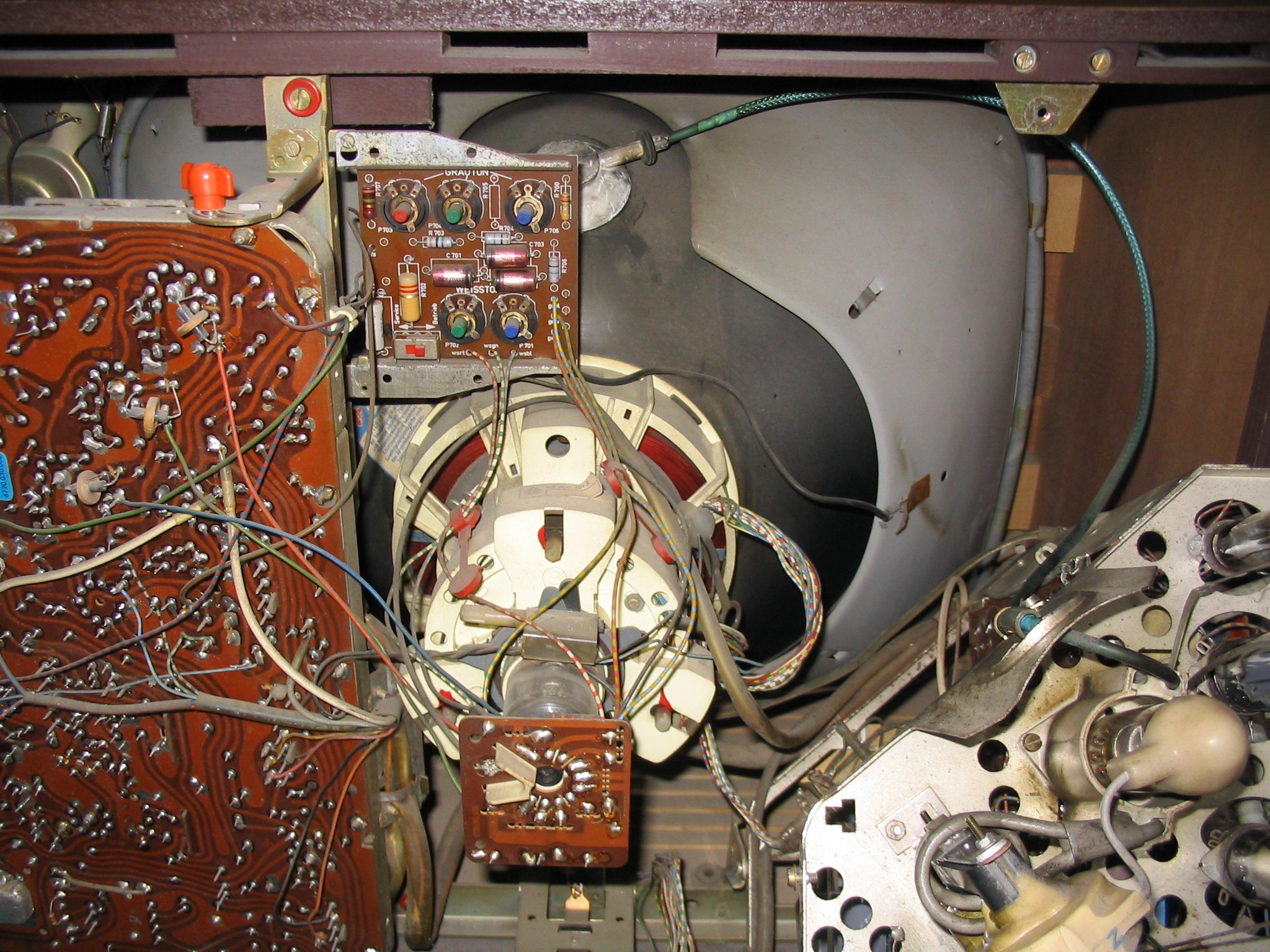
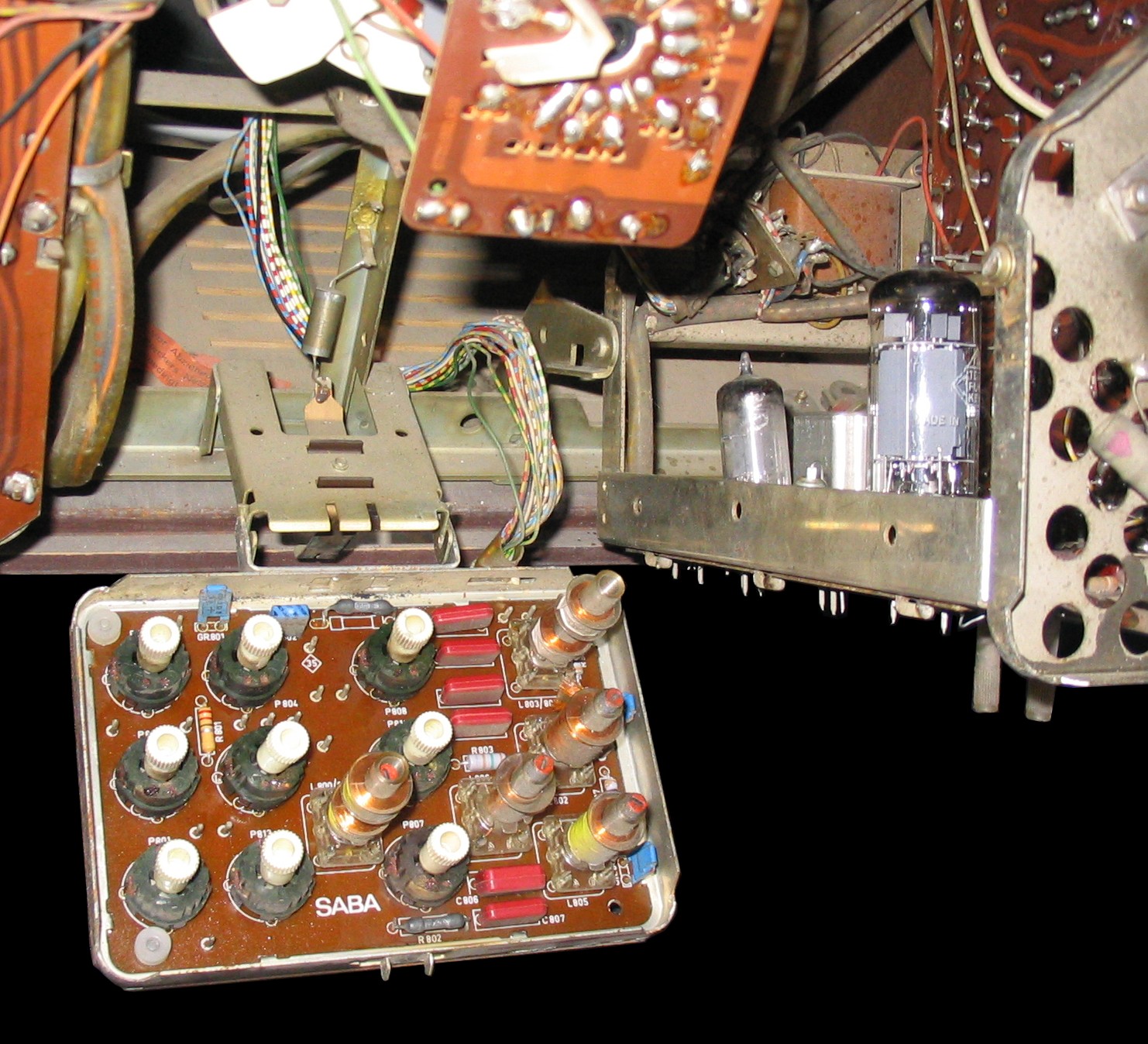
The potentiometers and the coils of the convergence are located on a board, placed below the neck of the CRT. The board can easily turn out for servicing.
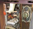
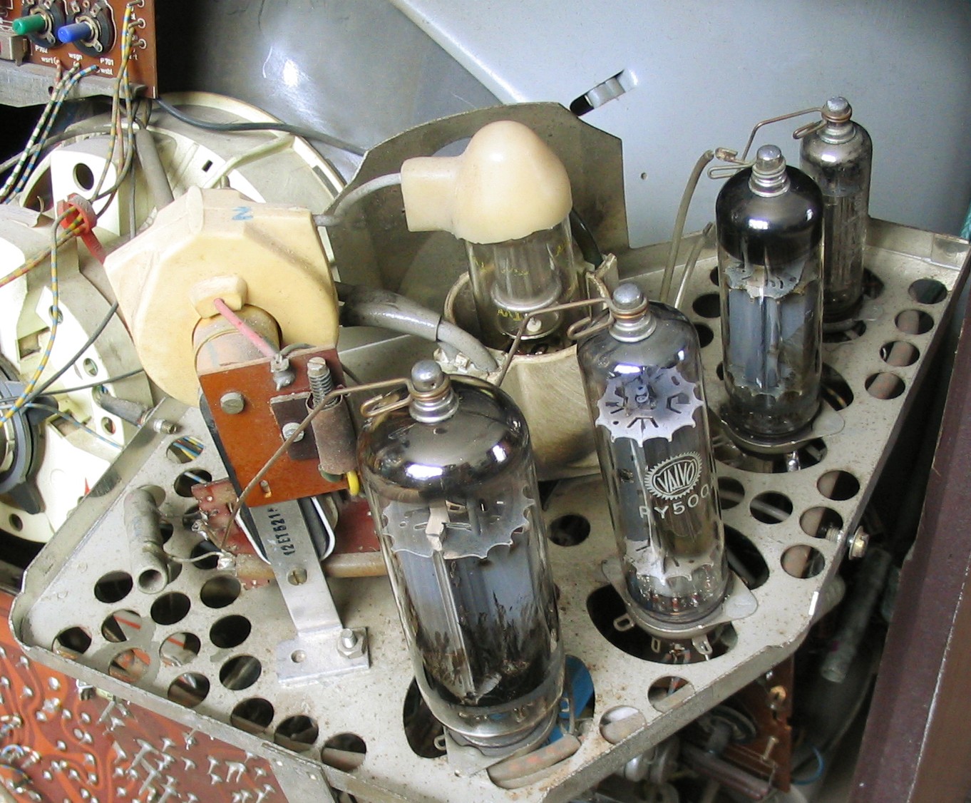
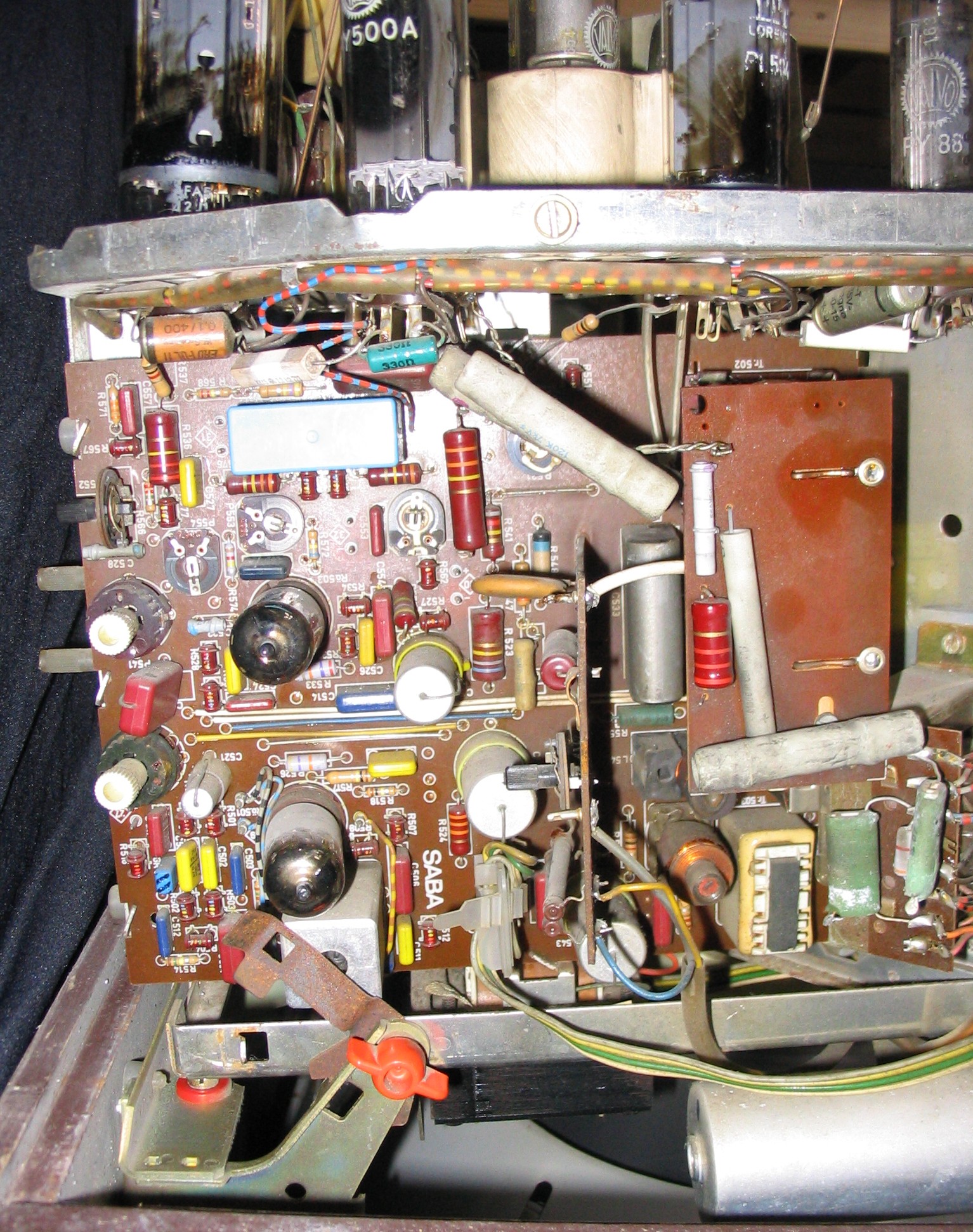
The television set documented here was defective when I got it. On the high voltage cage was a piece of paper with the writing "transformer defect". It was the line output transformer. While operating the set, there was no picture and the anode of the line output tube PL504 glowed – symptoms characteristic for this defect. Fortunately, some weeks ago I found a high voltage board from a Kuba colour television set with a similar line output transformer. I had no problems replacing the transformer. But when I switched on the set other defects appeared. The vertical linearity failed, and there was no picture synchronisation. This was caused by cold solder joints at the sync separation tube (PCH200). The bad vertical linearity was fixed by replacing the cathode electrolytic capacitor of the vertical output tube PL508.
|
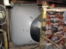
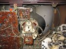
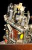
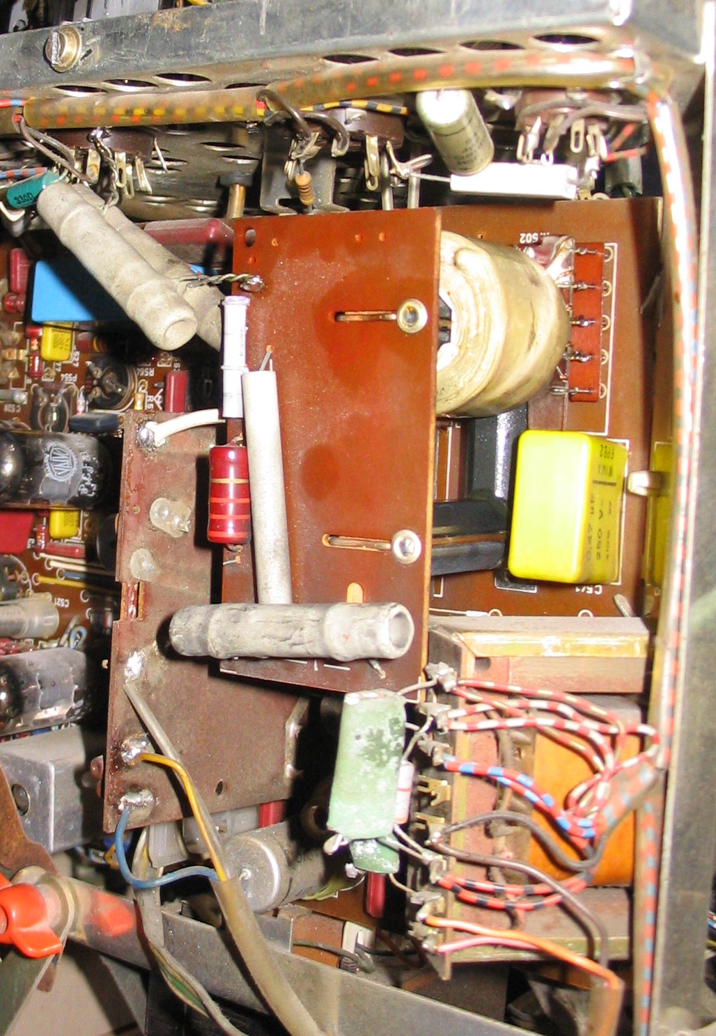
The vertical chassis on the right wing contains the deflection output units, the circuits which provide the currents for the convergence board, and the high voltage output unit. In the shadow mask tube design a large part of appr. 80 percent of the beam current is absorbed by the shadow mask and only a small part of appr. 20 percent of the beam current reaches the phosphors on the screen and illuminates them. A much higher beam current is required(25 KV with 1.5 mA / 40 watts, in comparison a b/w television set needs 15 KV with 0.2 mA / 3 watts). Very important is a stable voltage which is independent from current fluctuations, so that picture height, picture width, and focus remain on the same level. Well known is the method in the U.S. colour television sets with a shunt regulator, which consumes the high voltage current which is not needed by the CRT. Disadvantages of this method: the high voltage unit must produce every time the maximum current output. This results in additional heating and a shortened lifetime. And beside the high voltage rectifier the shunt regulator is a further source of dangerous X-rays. In the SABA Schauinsland T 2000 color the high voltage is generated in a separate unit from the line output unit. This high voltage unit makes possible a short-time high voltage current up to 6 mA (for a peak bright white on the screen) without a decrease of the high voltage of 25 KV. Another advantage: high voltage and picture width are independent from each other.
|
The circuits of the high voltage unit are similar to the circuits of the line deflection with a damper. But the energy is not stored in the deflection yokes but in the high voltage transformer. The high voltage output tube is the 30-watt pentode PL509. The high voltage generator is triggered by the line output transformer. A positive pulse of 370 Vpp is taken from the line output transformer. The advantage: when the line deflection declines, the high voltage declines too, and so the CRT is protected against damage. To avoid a feedback of the regulator current at the grid of the line output tube (PL504), an impulse-modulator tube (PCF802) was inserted. The independence of the high voltage from the beam current is realised by the impulse-modulator tube (PCF802). This tube works as a regulated rectifier. A positive pulse of 300 Vpp from the high voltage transformer is put on the anode. This pulse is rectified and results in a negative voltage. The height of this negative voltage depends on the grid voltage of the triode. Similar circuits are used in generating the A.G.C. voltage and in the colour killer. The negative voltage is put as a grid voltage to the grid of the high voltage output tube PL509. A part of the booster voltage of the high voltage unit will be put across a voltage divider on the grid of the regulated rectifier (PCF802). A part of booster voltage of the line output unit is put on the cathode of the PCF802 across a voltage divider (85 volts). Assume that the picture content changes in this way that the beam current increases, the high voltage decreases. According to the decreasing high voltage the booster voltage of the high voltage unit decreases too. The positive voltage at the grid of the PCF802 decreases, the negative voltage at the anode of the PCF802 decreases and the current of the PL509 increases so the decreasing of the booster and high voltage is corrected. A small error remains in counter-regulating like in every feedback-regulation. Now one can equalise this error too if one uses the beam current itself for the regulation of the high voltage. At the cold end of the high voltage coil is the high voltage control. If the beam current increases, the voltage difference increases, the positive voltage at the grid of the PCF802 decreases and the PL509 is powered up. The high voltage control is adjusted so that the internal resistance of the high voltage generator is zero or even negative. In practice the high voltage control is adjusted so that the picture width doesn't change while changing the beam current (brightness). The up to now described high voltage regulation circuit does work only for brightness changing on large screen surfaces. For regulating fast brightness changes a capacitor voltage divider is used which consists of the capacitance of the high voltage cable to the CRT (appr. 200 pF) and some more capacitors. If the high voltage decreases during a short interval peak brightness, this short voltage changing is acting via the capacitor voltage divider at the grid of the PCF802. Corresponding to this the PL509 will give more power for this moment, so the high voltage remains on the same high level. This results in a high brilliance and sharpness even in parts of a peak white on the screen. The reaction time is below 1 millisecond, a service which a shunt regulator high voltage generator couldn't provide. At peak white the high voltage unit can provide in connection with the very elaborated luminance amplifier for a short time beam currents of up to 6 mA (with nearly 900 mA cathode current at the PL509). This makes possible a stronger contrast control of the CRT A63-11X than in other colour television sets from this era.
|
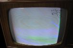
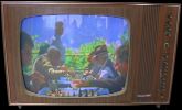
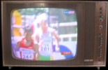
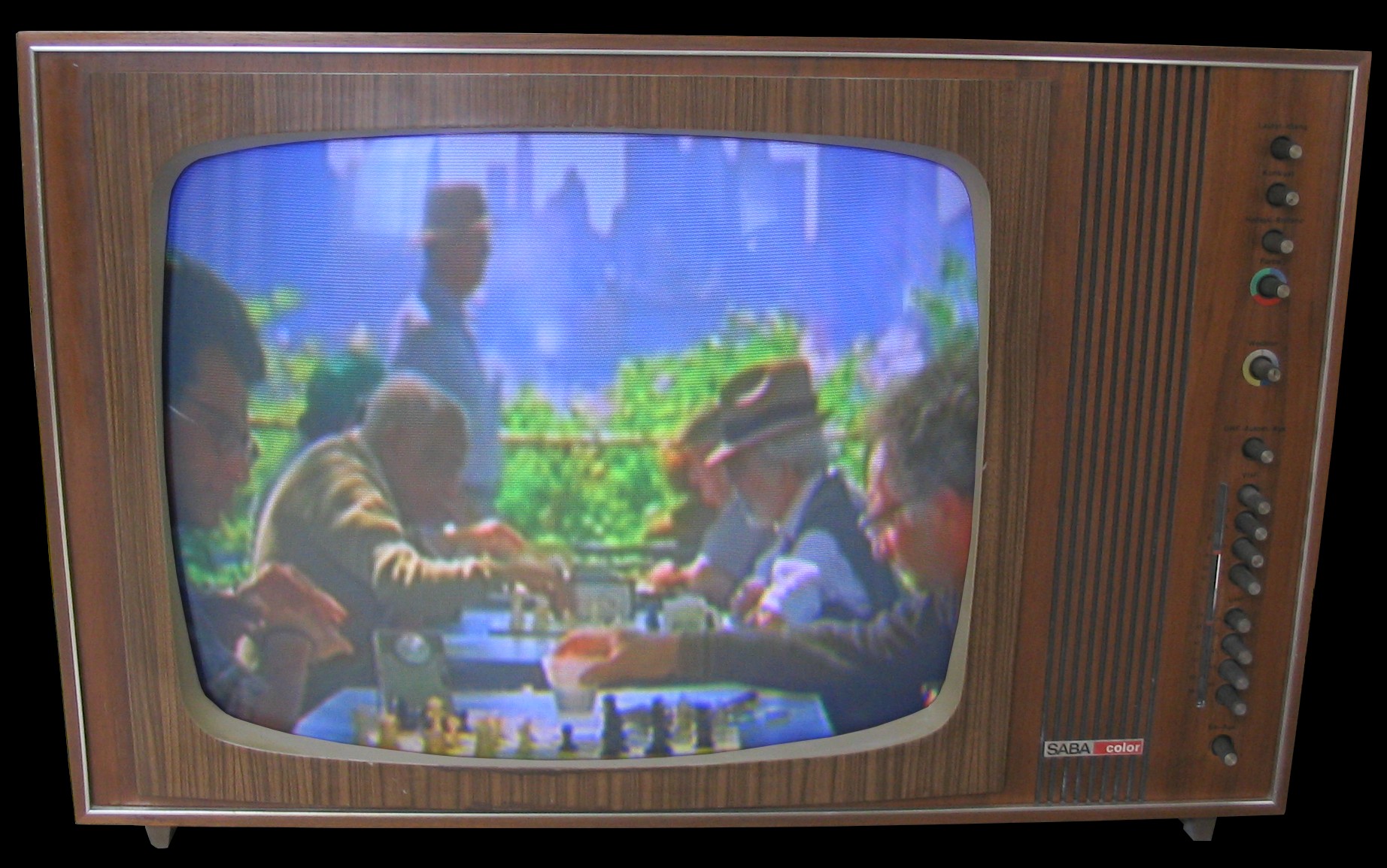
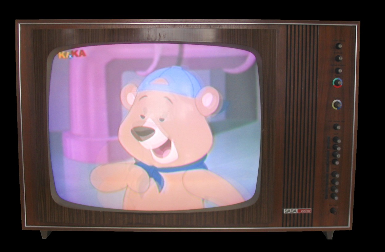
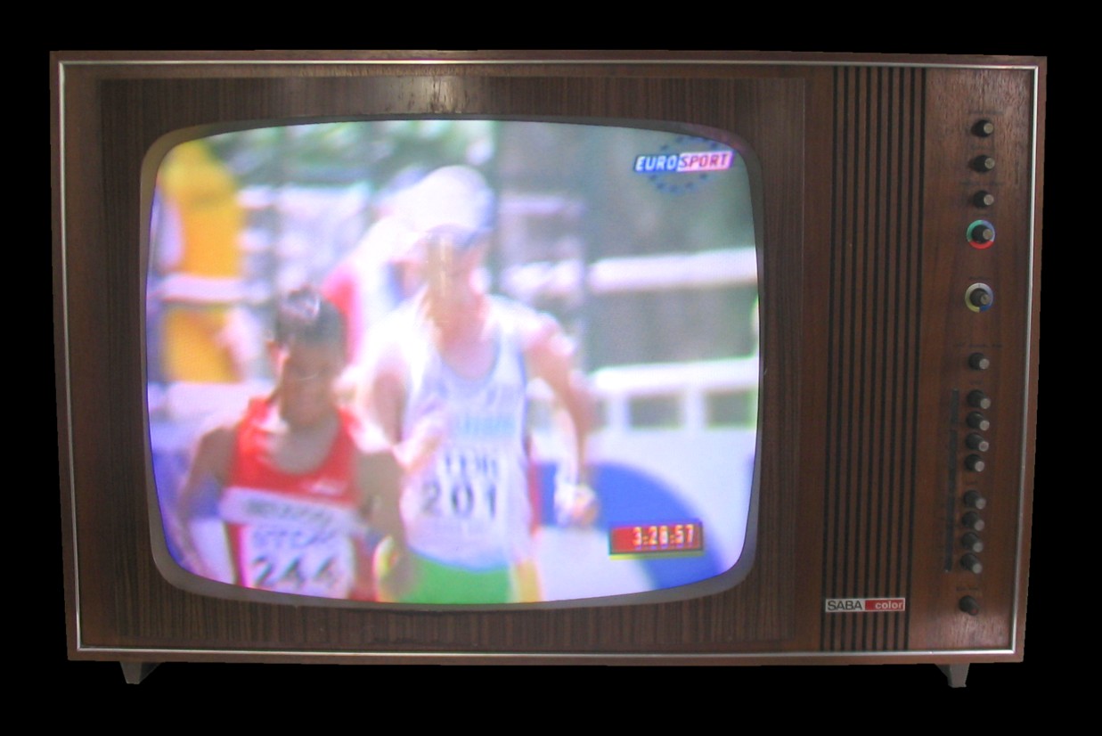
Left photo: the working television set after replacing the bad line transformer. (More photos: 1, 2.) Right photo: After fixing some small problems the SABA Schauinsland T 2000 color impresses with a gorgeous picture. Interesting is the advertising for the Saba 2000 color from 1967 which can be downloaded as a
powerpoint file here. With respect to black and white broadcasts, there was written: "The daily news, live reports and criminal tv shows will be broadcast forever in
black and white. The Saba 2000 color is therefore able to receive black and white broadcasts..."
|
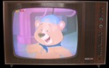
Two years after the set was repaired, the Saba color still has a good picture although the
picture tube was rejuvenated. The beam currents are 0.8 mA on all three guns, but measured with another picture
tube tester than the one with which the picture tube was rejuvenated. |
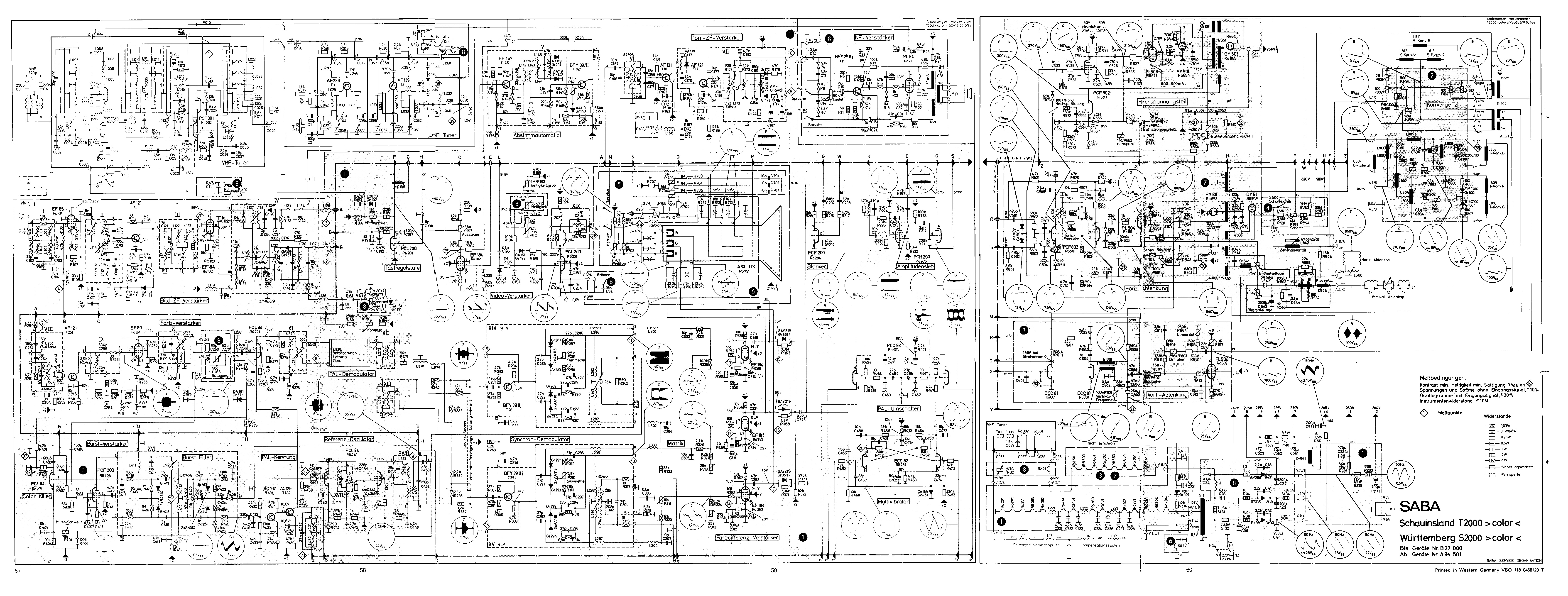
Schematics
as a TIFF-file (500 KByte).
Tubes
ECC81, ECC82, EF80, EF85, 5x EF184, DY51, GY501, PCC88, PCC189, PCF801, 2x PCF802, PCF200,
PCH200, 2x PCL84, PCL200, PL84, PL504, PL508, PL509, PY88, PY500, A63-11X.
Photos: © Eckhard Etzold 2005.
Thanks to Bob Gary for critical review of this text and many recommendations.
Links:
![[Zurück]](Images/arr-supr.jpg) ![[Text in deutsch]](Images/flag_de.jpg)
Stand: 19. September 2005, r
|


