|
Television Experimenters.com
Innovative Mechanical Television
If one mentions mechanical television, most readers will immediately have a mental image of a large disk rotating at high speed and providing a dim, small and coarse 24 to 60 line picture. Television began with scanning disks like one patented in Germany by Paul Nipkow in 1884. As work toward developing practical forms of
television began in earnest, it was soon became obvious that the scanning holes passed very little light. Even in full sunlight, early television cameras would not operate outdoors. There just wasn't enough light. The same was true at the receiver, where the light source was a flat plate neon lamp. The tiny holes in the disk allowed much less than one percent of the light from the lamp to pass through. It was really "lights out time" when a televisor was switched on. |

|
NIPKOW DISK
A bright picture would have been very welcome because it could then be enlarged by projection lenses and any added brightness would have increased the apparent resolution. By increasing the diameter of the Nipkow disk, larger scanning holes could be used. This explains why disks tended to be from two to four feet in diameter.
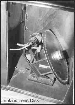
An early improvement over the Nipkow was the lens disk. Lenses were added because they could pass much more light than the scanning holes. When lenses were used, their optical centers were located in the same place as the scanning holes in a Nipkow disk. John Logie Baird of Scotland had built lens
disks as much as eight feet in diameter, (think about that for a moment!) with 30 lenses as large as bowling balls.
He was once almost killed when some lenses came loose while one of these large disks was in operation, throwing everything out of balance. The lenses were flying around the room like large boulders and he wisely took cover.
|
 |
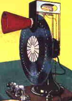 |
One good thing about using Nipkow disks was that the receivers were simple and easy to build by the experimenters and many did. Numerous magazine articles were published for those interested in building their own and kits were available too. Most of the radio amateurs of the day could readily "scrounge up" the necessary parts to build one.
The one pictured here used an electric fan for the motor and a 16 inch transcription record for the scanning disk. The light shield was a small megaphone. |
As photo cell sensitivity and light sources improved, scanning hole size or
lens diameters could be reduced.
Reducing the disk size resulted in a more compact scanning assembly. As
an example, Western Television of Chicago produced a televisor with a
17 inch aperture disk and a flat plate neon lamp. It provided a 45 line, 1
1/8 by 1 1/2 inch picture.
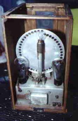
The following year (1931) they developed this new 45 line model (rear
view) with an 8 inch diameter lens disk. It provided a much larger and
brighter picture, measuring about 4 by 4 inches. The improvement was
due to the use of both the lens disk and a more efficient light source, a
crater arc neon lamp. This new model included an 8 tube receiver, which
the previous model did not and the complete receiver occupied only
about half the table space as before. |
 |
An Explanation About the New 12 inch, 32 line Scanning Disc (available on this site)
The usual 32 line scanning disc has one continuous spiral of 32 holes with a fixed pitch of image forming holes occupying one complete rotation of the disc, equivalent to 360 degrees.
The new scanning disc has a fixed pitch spiral extended for an additional one half rotation of 16 holes or 180 degrees, for a total number of 48 image holes.
In receiver operation, the first 32 holes (#1 thru #32) are exactly one turn in the spiral of image holes. These along with the appropriate Light Source (LEDs) will provide the receiver image to the viewer/operator.
In camera operation, the first 32 holes are used with an appropriate camera lens, signal amplifier and photo cell to process the image. For the monitor function, use holes (#17 thru #48) along with the suitable Light Source (LEDs) and a simple image
magnifier.
Additional Remarks - Regarding Mechanical Television Receiver
Lenses designed for 35mm camera equipment are suitableHoles #1 and #2 straddle the image at the very top of the disc
Holes #33 to #48 are not used if there is no monitor function. Cover the holes with Room Temperature Vulcanizing Rubber (RTV)
Additional Remarks - Mechanical Television Camera with Monitor
Lenses designed for 35mm camera equipment are suitable Holes #17 and #18 straddle the monitor image directly below the holes #1 and #2. The Monitor image is formed using holes #17 thru #48
|

All rights reserved.
|