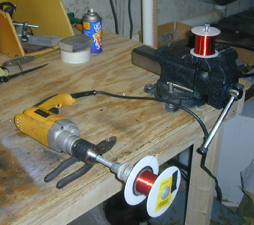
Early Electronic Television Baird T-18C RestorationThe cabinet of this set is in horrible condition. It has obviously been sitting in someone's storage shed for years, and has been damaged by water. The CRT has been damaged and is probably full of air. It appears that a postwar tube will fit perfectly, and will work with minor modification to the set. There is also a strange pilot lamp mounted inside the cabinet near the CRT. It illuminates the rear of the CRT screen with an orange glow when the radio is in use. Here is technical information on this set. Cabinet. (pictures) The cabinet will require a full restoration. Perhaps some of the original veneer can be salvaged, but most will have to be replaced. There doesn't appear to be worm damage, however. Restoration of the cabinet is complete. Chassis. (pictures) There are two chassis in this set, the Radio/Power Supply Chassis and the TV Chassis. These chassis have a considerable amount of rust on them. Each chassis will be cleaned with water and a mild detergent using soft brushes to get into small places. We will attempt to clean the rust off the chassis, and have the detachable parts replated. Then, all paper capacitors will be replaced with modern ones (see the procedure for this). Each electrolytic capacitor will be tested for leakage and capacity. If bad, new electrolytics will be installed inside the old ones. The high voltage (EHT) capacitor also had to be rebuilt. We have no technical information on this set, so we will have to trace the circuit diagram. After inspecting the chassis, I determined that the rust was too severe to be removed. So, all of the components have been stripped off the chassis, and they will be taken to be replated. The chassis have been replated. Radio/Power Supply Chassis: This chassis has the B+ (HT) and high voltage (EHT) power supplies, and the radio circuitry. The tubes (valves) in the radio section are TH3B (triode-hexode first detector), VP4B (IF amplifier), 2D4A (detector), SP4B (audio amplifier) and AC4PEN (audio output).The B+ (HT) rectifier is apparently a UU5 and the high voltage (EHT) rectifier is apparently a HVR2. I have reassembled the Radio/Power Supply chassis. Since we have no schematic diagram, I have been tracing the circuit as I go along. There are a couple of unusual features. First, it appears that the filament current for the CRT was critical, and the set has a set of jacks to adjust it. Second, the audio amplifer (SP4B) also serves as a 41.5 mHz preamplifer. The sound RF is sent from the TV chassis. I am not certain yet whether it is further amplified at 41.5 and then detected, or if it is down converted to the radio IF frequency. The 41.5 mHz TV sound is down converted to 456 kHz in the frequency changer. The TV sound works fine now, but the radio doesn't. The local oscillator works on all three bands, but there is no IF output. The problem may be in the antenna coils, which I may have connected improperly. I found a couple of schematics of Bush radios from that era (Bush made Baird TV sets before the war) that look similar. That will help find the problem. Since I haven't yet rebuilt most of the paper capacitors, one or more of them may be bad. The problem was a couple of wiring mistakes I made when reassembling the chassis. It now works perfectly. The speaker field coil winding is open. I dissassembled it and could find no obvious fault, so rewinding was the only option. Using a jig made with an electric drill I wound over 3000 feet of 30 ga. wire onto the old form. 
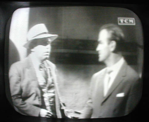
TV Chassis: The other chassis has a brass RF section with tubes (valves) inside. This contains the RF amplifiers and detector. On the chassis there is a AC2/HL valve, which is the sync amplifier, and five tubes (valves) used in the sweep section. The horizontal (line) sweep uses a 2D4A diode, a AC/P output tube, and a UR1C damper. The vertical (frame) sweep uses another 2D4A diode and a AC/P oscillator/output. A strange transformer is used in this set. It has an extended frame which comes up around the picture tube. This transformer serves as both the vertical (frame) output transformer and deflection coil. I have reassembled the sweep portion of the TV chassis. I have a schematic diagram of a similar set's sweep circuits, so tracing this set's design was easy. I have rebuilt the electrolytic capacitors, and now must rebuild the paper ones. The paper capacitors have been replaced, and the horizontal (line) and vertical (frame) sweep circuits appear to work properly. I have now started on the RF module. It contains three TSE4 tubes (valves), two as RF amplifiers and one as a video amplifier, plus a diode detector. The RF module now works. I have now tested the entire set, and everything appears to work. I am missing the horizontal (line) oscillator tube (valve), and I am attempting to have the CRT (Baird Cathovisor) rebuilt. I now have the tube (valve). I have installed a Mullard MW 31-18 postwar CRT in the set. It is physically about the same size, but has a very different gun. The original tube has the cathode tied directly to the filament internally, and is a triode. The filament operates on 2 volts. The MW 31-18 has a 7.5 volt filament, a separate cathode lead, and is a tetrode. To get the required filament voltage, I connected the 2 volt supply in series with the 4 volt supply used for the other tubes (valves) in the set. There is a plug/socket assemly to match the CRT filament current. By using the lowest setting I was able to get 6.3 volts. I connected grid #2 of the new tube to a source of about 150 volts in the set, and slightly changed the brightness circuit. I now have an excellent, stable picture. 
The MW 31-18 is about an inch longer than the original tube, so the chassis sticks out of the rear of the cabinet. I am hoping that the original tube can be rebuilt. |
