Early Television  
Mechanical TV History How it Works Mechanical Sets at the Museum Gallery Database Summary Broadcasting Technical Inforation Restoration Advertising Articles Roger DuPouy's Site Peter Yanczer's Site Gerolf Poetschke's Site Eckhard Etzold's Site
Early Electronic Television History American Sets at the Museum British Sets at the Museum Gallery Database Summary Broadcasting CRTs Accessories Technical Information Restoration Advertising Articles Gerolf Poetschke's Site Eckhard Etzold's Site
Postwar American TV History American Sets at the Museum British/Europen TV History British/Europen Sets at the Museum TV in the Rest of the World Gallery of Unusual Sets Broadcasting CRTs Accessories Technical Information Restoration Advertising Articles Eckhard Etzold's Site
Early Color TV History Sets at the Museum Gallery Database Summary Broadcasting CRTs Accessories Technical Information Restoration Advertising Articles Pete Deksnis's Site Ed Reitan's Color Television History Eckhard Etzold's Site
The Early Television Foundation About the Museum Directions to the Museum Articles about the Museum Support the Museum Join our Email List Our Newsletter - "What's New in Old TVs" Equipment Donations Museum Members and Supporters Members Only Monthly Online Meetings Annual Convention Swapmeets
What's New on the Site Classifieds Parts for Sale Resources North American Radio and TV Museums Search the Site
Contact Us Facebook YouTube Channel
Early Television

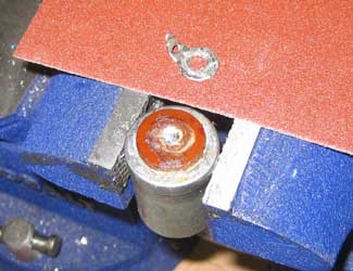
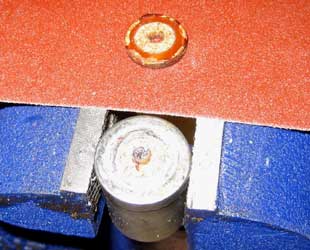
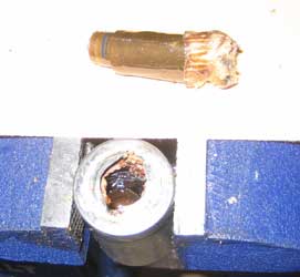
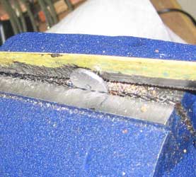
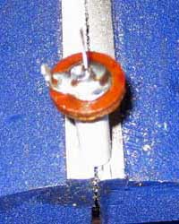
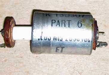
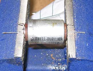
Rebuilding High Voltage (EHT) Capacitors

Often the high voltage (EHT) capacitors in early electronic sets are bad. They can be rebuilt using modern parts inside the old cans. Here is the process I use.

Can Style

Early Television

First, the capacitor is opened up. In this case the can is mounted to the chassis with a bracket around its base. The can is cut so that the cut will be hidden by the bracket when installed. For screw mounted capacitors the procedure described in the section on rebuilding electrolytics can be used to open the can.

Early Television

Next, the guts are removed. In this case, two holes were drilled in the material inside the can, then the jaws of needlenose pliers were used to remove the material. A heat gun melted the wax at the end.

Early Television

Then, modern capacitors are grouped together to provide the values needed. This capacitor had a .05/3000 volt and a .15/3000 volt section. For the .05 section, 5 - .01/4000 volt capacitors were used. For the .15 section, 3 - .05/4000 volt capacitors were used.

Early Television

The assembly is connected to the existing leads. Instrument wire, with a rating of 6KV, is used. The center wire is ground (earth).

Early Television

The assembly is wrapped in high voltage insulating cambric cloth to assure it doesn't arc to the can.

Early Television

Finally, a glue gun is used to apply hot glue to the fabric and the two pieces of the can. After cleaning the can is ready to be re-installed.

Cylindrical Soldered Can Style

Early Television

Early Television

First, remove the solder from both ends

Early Television

Use a 1/4 inch drill to drill through the top so that the ring can be removed

Early Television

Drill further to remove the fiber insulator

Early Television

Elongate the hole in the can to remove the metal piece and the old capacitor

Early Television

Cut off the small portion of the metal piece that was removed

Early Television

Solder the new capacitor to the ring and the small portion of the metal piece

Early Television

Slide the assembly into the can

Early Television

Use superglue to attach the wafer to the can, then clamp it until the glue dries. Then cut off the excess lead length and solder the ends.


Early Television Museum
5396 Franklin St., Hilliard, OH 43026
(614) 771-0510
info@earlytelevision.org