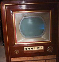
THE SETRestoration Log06-26-2005 This new restoration log page introduces a new CT-100 to the restoration spectacular.
I was fortunate to have acquired a second Merrill in August 2004 after nearly a year of negotiations. It is chassis number B8000194, a brother to my original CT-100. This Merrill was rolling down the Bloomington assembly line just hours behind B8000173, the Merrill that spawned this site in 1999. They are virtually identical in terms of production strategy. With the B8000194 chassis, I initiated a restoration process anew by following the approach set down in the first four restoration logs. Those early logs were meant to repair an ancient CT-100 and return it to operation. This continuation of that process, however, is designed to improve the reliability of a CTC-2 chassis as well as to repair it -- a true
restoration
.
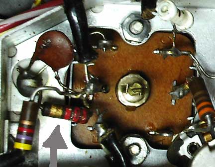
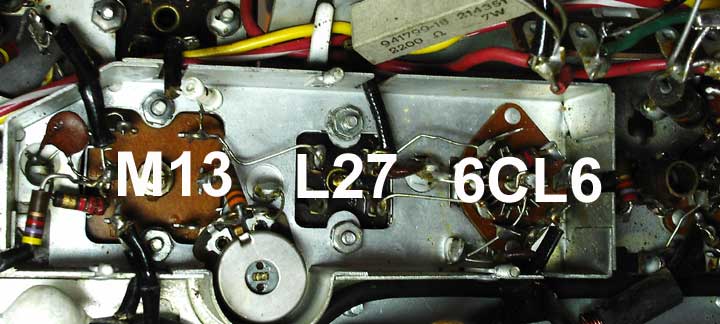 Perhaps it contributed to the abandonment of this Merrill in 1956. Note the 2.2K, 1/2W, 5% carbon resistor connected to terminal 'E' of M13 and ground, shown close-up below, see arrow. This resistor is damaged and varies in resistance from 10K to over 100K. It is the lower component of a two-element resistor divider that drops the 275-volt bus to about 3 volts and is used to contribute bias to the first video amplifier, or so it should.
Fortunately, the overvoltage that occurs when the 2.2K resistor drifts does not damage M13 circuitry, including its 1N60 second detector, but it did play havoc with the video-amp bias.
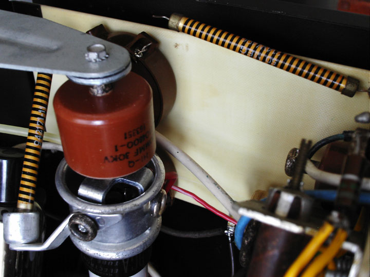
The replacement resistor was relocated outside the shield so that I could more readily monitor the drop across the 2.2K. ------------------ (2) Smell the ozone… Two 50-meg ‘barber pole’ resistors in a series string with the 15-meg convergence pot in-between are connected from the 19.5-kV high-voltage to the top of the 1-meg high-voltage adjustment pot, which itself is 1.8 megohms above ground. Phew! The point is: The metal end-cap of the second 50-meg resistor, R185, was arcing to the phenolic mounting board. If you look carefully, you can probably see two dark smudges caused by the arcing, which occurred where the end-cap hovered before the lead was cut.
A search through the Allied on-line catalog found a 100-megohm that was rated for the high voltage found in this circuit. As seen next in a bird's-eye view, a parallel-connected pair of the flat resistors fit nicely in place of old sparky. No more ozone.
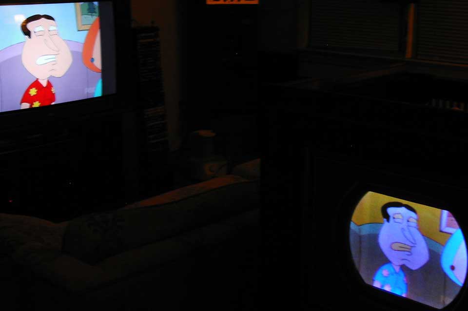
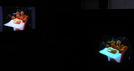
------------------ (3) 07-01-2005 Andorian (think Star Trek) Effect. Here's the biggie. Hue, or color, is determined in the NTSC system by the phase of a sideband. The amplitude of that sideband controls the intensity of the color. An oscillator in an NTSC color receiver generates a signal used by the set to recover hue and intensity from an NTSC color broadcast signal. The oscillator must be extremely stable; a slight change in the frequency of the oscillator will cause the recovered color to be incorrect. In fact, the 'frequency' stability is measured in terms of phase because it defines accuracy to a fraction of one cycle of the oscillator frequency. Phase is measured in 'degrees.' There are 360 degrees in one cycle. When the phase of the oscillator in an NTSC color set is not what is correct for a given color, that color on the screen will be wrong. In Merrill B8000194, there seem to be somewhere around 90 degrees of incorrect phase. The result is the Andorian effect. Check the 'red' shirt on Merrill B8000194 in the lower right.
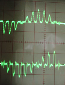
An NTSC color broadcast signal actually has two sidebands to carry color and intensity; they are called I and Q. When the information in the I and Q sidebands is recovered, or demodulated, and viewed on an oscilloscope, both channels are clearly seen to be operating. (A gated color bar generator signal is applied to the rf input in this example.)
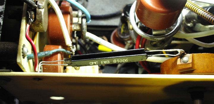
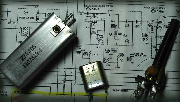
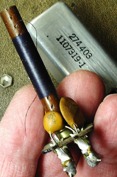
For stability, the oscillator in a CT-100 is crystal controlled. But that alone is inadequate. An NTSC color television transmitter provides receivers with a reference signal that allows the receiver to 'lock' itself to the transmitter reference signal. Which all works together to get the colors on the screen correct. Some of the components in a CT-100 that are used to lock onto the transmitter reference signal and generate correct hue are the crystal (3579.545 KC) and a control system that includes a CHROMA REFERENCE OSC CONTROL stage and transformer 1107319-1 (L43) shown here disassembled.
atastrophic because the transformer that is part of the chain controlling the crystal-controlled-oscillator (V29B) phase was damaged, as is evident by the flying lead from the transformer winding.
Once repaired, the set displayed stable color, but Andorian-effect color. That state exists to the present day even after installation of missing inductor L42. T'shooting continues...
|