THE SETrestoration log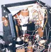 1. 5-31-99 Clean-up time in the cage. This high-voltage cage contains the 1X2 focus rectifier, 3A3 high-voltage rectifier, and the 6BD4A shunt regulator for the 19.5 kV second-anode voltage.
 Forty-five years and two months worth of dirt and crud were removed from the dismantled cage assembly. Disassembly was relatively simple and logical. After removing the tube-access shield (shown here removed), six screws allowed a steel plate to be removed from the opposite side, revealing the focus and convergence potentiometer mounting nuts and their phenolic mounting plate. I backed out four more screws to free-up the plate and expose more wiring and give me access to more of the thick blanket of congealed dust and crud covering the floor of the cage, which is nothing more than a restricted area of the main chassis. Nearly the entire cage assembly can be dismantled without resorting to desoldering. It is my hope to replace only what is designed to plug in. The object is to keep the set as close to original as possible. To that end, wherever possible, a removed screw went back into the same hole it had been filling for forty-five years. The lockwasher and nut on the focus and convergence potentiometers were returned to their original locations - neither were flipped upon reinstallation. Also, the twin phenolic blocks that guide the high voltage lead from the cage were reinstalled precisely as they had been during manufacture. You can be certain that I'm trying to be careful and not damage anything during restoration. But you can be just as certain that something is going to slip through the proverbial crack. Here's what happened first time out. As I disassembled the convergence potentiometer (3R254) that taps the high voltage through a 50-megohm high-voltage resistor (3R253), suddenly one end of 3R253 was floating in space, connected only by the other pigtail lead to the high end of the convergence pot. Damn! Well, it turns out that 3R253 mounts to a special socket in the corona ring of the 3A3-cathode (high voltage) terminal, much as a plate cap connector fits onto its plate cap. Everything went back together later just as it was designed to. Hope I never need to jury-rig that 50-megohm high-voltage resistor with a metal terminal, that fits into a corona ring, that has an unknown power-rating, that.... I've suppressed enough high-voltage arcs at CRT terminals over the years to realize the importance of a clean, dry, high-voltage cage. So sure, I spent the best part of Memorial Day 1999 blissfully ignorant of the world around me, communing with my cage. But so what? A spiffy clean HV cage is the first small step! 2. 5-31-99 Previously on "The Practice".... With kudos to "Star Wars I" and my favorite tee vee show, here's a quick prequel. About two months ago I retrieved my CT-100 from storage where it had languished for the last fifteen years. Set it up in my living room (one can do such things when the wife is an ex.) and fired it up WITHOUT the high voltage. (Just pull the 2P101 ballast resistor; there's an interlock that opens the power transformer low-voltage-supply winding.) What a sight. All those glowing embers. Turn out the lights. Looks even better. What's burning? What's that odor? It didn't take long for all the years of dust and crud to start cooking and get real smelly. So I cleaned the stuff off the tubes: the next time those fils get hot, it should be sweeter. And finally from this Memorial Day eve: earlier in the day I Ecom-ordered an NOS RCA 6CD6G (horizontal output) and an NOS RCA 6SN7 (horizontal oscillator and control) from Michael Tannenbaum k2bn@agtannenbaum.com. Never dealt with him before. Let's see what happens. The 6SN7 was missing (what'd I use it for?); the CBS 6CD6GA (date-code 6043) is full of air. 3. 6-6-99 Added a table listing all tubes and what I believe are original tubes from 1954. About one-third of the 36 tubes are probably original. 4. 6-12-99 Added menu page where theory of operation of specific circuit functions is presented along with any hands-on information of note. Located in the restoration menu. 5. 6-23-99 Spent a few hours cleaning and scraping around the tuner and power supply. After removing four screws that secure a vertical mounting plate to the main chassis, I had to cut (1) the 380-volt line from its rectifier and (2) one of the pigtail leads of a fuse. That provided enough movement of the plate to properly clean the area around the filter caps in the voltage doubler circuit. The vertical chassis holds selenium rectifiers, field-neutralization and purity-adjust potentiometers, two pigtail fuses, and two sockets (yes, for the field neutralization and purity coils). Another fuse on the assembly is cracked in half. Both original fuses had been bypassed with clip-on replacement fuses sometime before I owned the set. Also cleaned the top of the tuner. Popped off the cover protecting the turret in the tuner from dirt. All the vhf guys were in there, but all four of the uhf strips were dummies. This set had never been configured to receive uhf. Was that standard practice? Probably. Didn't the first uhf station go on the air in 1952, only two years before this set was built? They never did become as popular as expected. I know of two uhf stations in the Bethlehem, Pennsylvania area that had gone belly-up and off the air by 1957. Anyway, the mixer diode in the tuner is a K3E type, which I suspect is probably just a fancy, maybe selected, 1N82. What I do know is that this one is open to the elements. It's user (repair-guy) replaceable for some reason, so it was particularly cruddy. The axial contacts fit into a pair of tong-like contacts in the tuner for a rather loose fit for so critical an RF component. I used contact cleaner all around after cleaning the diode contacts with bits of soft paper towel. Looks good. It should do its job. 6. Read next log entry in the next restoration menu link. Last Updated 7-28-99, 11-23-01, 5-18-02
|