|
The Set: Pete Deksnis's Site about the CT-100 Restoring a Vintage Color Television Set THE SETQ Filter InvestigationI had an opportunity to investigate an interesting question concerning the use of approved substitutes for original manufacturer’s parts. I obtained a replacement inductor from CT-100 caretaker Tim Moritz that had been received from Terry Wise, who acquired three samples from J.W.Miller in Gardena. CA. The part is used in the Q filter of a CTC-2 chassis and is listed in the 1954 Sams Photofact for the RCA CT-100.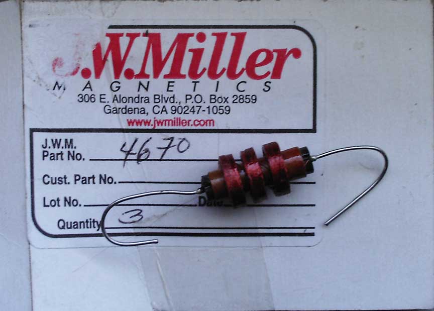 Preliminary. An NOS Miller 4670 inductor (above) was substituted for RCA part 78902 (below). The Miller 4670 inductor is listed in the Sams 252 Photofact as an approved substitute for the original RCA production part. This is one of five NOS inductors available from Miller as of June 2005. 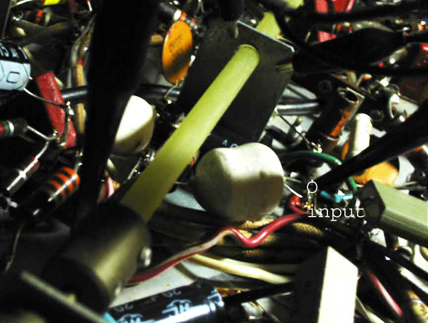 In a Nutshell. Before the Miller inductor was substituted for the original RCA part, operating characteristics of the Q filter were investigated as follows. With the restored CTC-2 chassis tuned to an OTA color broadcast and the Color control fully CCW, the input (see above) to 2L122 (L46 Sams) of the Q filter was 7-volts p-p. The output from the Q filter network was approximately 0.2-volts p-p. 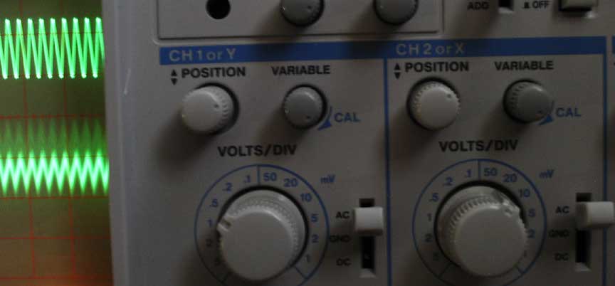 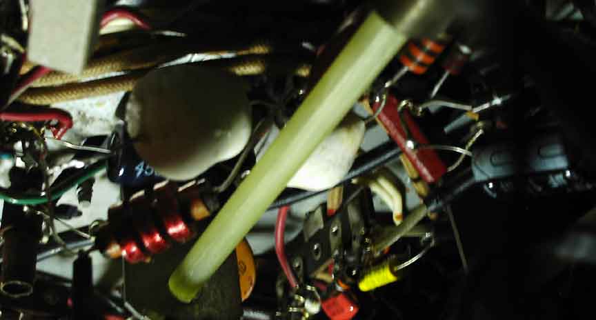 After the Miller inductor (above) was tack-solder substituted for the original (now disconnected) RCA part, the input to 2L122 (L46 Sams) of the Q filter was still 7-volts p-p. The output from the Q filter network was approximately 0.4-volts p-p.  During the time the replacement Miller 4670 was installed (about two weeks) the hue could be set for acceptable face color or acceptable everything-else color. December 24, 2006. I returned CTC-2 B8000194 back to its original restoration configuration by replacing the factory-original 6.7-mH RCA inductor in the Q filter. When I restored the RCA inductor, there was an immediate return to acceptable facial hue and acceptable everything-else color. Also, the Miller replacement appeared to require greater Color gain than did the RCA coil. Conclusion.Without a suitable spectrum analyzer to inspect I and Q sidebands of a test signal, my conclusion is drawn only from the difference in color subcarrier voltage present at the output of the Q demodulator. Because the quiescent signal at the output of the Q demodulator was at least twice the level with the replacement inductor, it suggests the slope of the filter is less steep and therefore probably results in crosstalk, where some of the unwanted lower I sideband contaminates the desired Q signal. Not being able to balance the hue control with the replacement inductor in circuit seems to support the inference. Theory. A familiarity with the balanced modulator and its use in coherent detection is assumed. Color information is transmitted in the NTSC color television system by two signals, I and Q, named for the type of amplitude modulation used to convey the signals to a color television receiver. The Q signal is 0.5 MHz wide and transmitted as a double-sideband suppressed-carrier signal. The I signal is 1.5 MHz wide but transmitted as a vestigial-sideband suppressed-carrier signal with its upper sideband limited to 0.5 MHz. Therefore, both the I and Q upper sideband signals extend up 0.5 MHz, while the lower sidebands extend down to 0.5 MHz for the Q and 1.5 MHz for the I. Since it is characteristic of a balanced demodulator to reject modulation in quadrature with its reference, the I balanced demodulator rejects the Q (quadrature) sidebands. The Q demodulator, however, is presented with something different — it is a lower I sideband that can extend beyond the 0.5 MHz bandwidth of its upper (I) sideband. It is a further characteristic of a balanced demodulator that only a double-sideband signal in quadrature will be rejected, and so a Q demodulator does not reject the extended-bandwidth portion of the I signal; it will only reject the double-sideband portion of that I signal. The unwanted 0.5 to 1.5 MHz lower sideband will appear in the output of the Q demodulator. Therefore, the output of the Q demodulator must have the unwanted 0.5-to-1.5 MHz lower I sideband signal removed, and that’s easily done with a low-pass filter. In the CTC-2 chassis, the low-pass filter consists of 2L122, 2C266, and 2R321. Inductor 2L122, a 6.7-mH peaking coil in a low-pass filter, was the subject of this investigation.  (Created Dec. 29, 2006. Revised 'Theory' 12-31-2006)
|