|
Television Experimenters.com
Synchronous or Synchronized ?
Which is the Best Way to Go?
The subject is motors, the prime mover for scanning disks (and could do the job, but each has its share of advantages and disadvantages. But before we discuss that, let's consider the problem.
Say that you have a camera with some sort of motor driven scanning device. It's important that the motor operate at a constant speed, both in the short term ( less than one revolution) and long term, measured in hundreds of revolutions.
This will assure that each line of video information generated by this camera will have the same time period
The receiver in turn must reproduce each line as it arrives from the camera, placing each image element in the appropriate position, just as it was at the camera. The only way this can happen is if the receiver disk is in the exact same relative position as the camera disk (the same phase) and the RPM of the two motors is also the same and remains so. When this happens, it is said that the motors are "synchronized." |
|
|
In their earliest work of some of the first experimenters used a line shaft some 4 to 6 feet long and driven by a single motor. They then placed a light barrier, usually a curtain or a wall between the disks
so that strong lighting could be placed in the vicinity of the camera disk without interfering with the viewing disk. Set up in this manner, the disks were absolutely synchronized. A bit later, wanting to separate the camera from the receiver, J. L. Baird used variable
speed motors with a small AC generator connected to the motor shaft. |
He used this arrangement at both the camera and receiver disks, placed a room apart. By the adjustment of speed. He then connected the two alternators together with a switch and the two disks would immediately begin running at the same speed and phase relation. This was the method of synchronization he used in his color television demonstration of 1928.
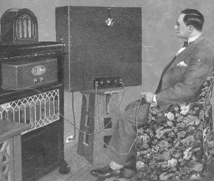
In the time frame of 1928, there were two ways to accomplish synchronization in the early mechanical systems. The first is to have a synchronous system, where all of the motors were of the sort that would run synchronous to the AC line frequency. However, in 1928 the typical electrical power station supplied relatively few customers. As a result, there were numerous comparatively small power stations spread throughout the United States. This severely limited the number of potential viewers, because if a viewer were located in a different electrical power grid, there was no way to hold synchronization with the television station. Instead, a variable speed motor was used with a speed controlling rheostat on the end of a cable long enough to reach to the viewer. Using a "course control" rheostat and setting it to cause the motor to operate at the approximate correct speed, the rheostat given to the viewer then provided a "fine control" and final adjustment for speed. The fact was that final-final adjustments would be required every few seconds. This 1928 photo shows Hugo Gernsback watching television. Note the wire to the rheostat in his left hand. If viewers could see a recognizable image for more than a few seconds, they would be delighted. |
 |
 |
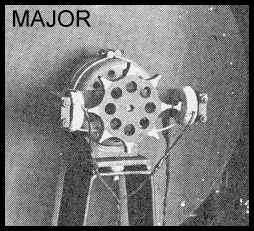
The second way to achieve synchronizim was to drive the disk with two motors, one much more powerful that the other. The larger, or "main " motor was an AC or DC variable speed, rheostat controlled motor. These motors were usually of a variety that used brushes and had relatively poor speed regulation characteristics, but induction motors were also used. Coupled to the same shaft was a secondary or "synchronizer" motor. This motor's winding was supplied by either the AC line or by an amplified form of the line scanning frequency derived from the television stations signal. In the latter case, the smaller motor was known as a "phonic" motor. It was easy to tell the difference. The AC operated synchronizer was a true synchronous motor and had 6 or 8 "teeth" or poles on its rotor, depending if it ran at 900 or 1200 RPM. The one shown here on the right was used in an English "Major" receiver and it has 8 poles. Because the receiver and the synchronizer operated from 50 Hz power, the synchronous speed of this 30 line disk was 750 RPM. This provided 12.5 image frames per second. The company also provided a 30 tooth phonic rotor to those who needed it.
|
|
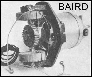
The "phonic motor" on the other hand had a rotor with 24, 30, 48 or 60 "teeth" or poles, depending if there were 24, 30 48 or 60 lines in the picture. The one pictured here was used on the Baird "Televisor". The rotor has 30 teeth and the disk speed was approximately 750 RPM and synchronous to the signal. The coil drive signal for the phonic motor was derived by filtering it out from the picture signal and then sometimes
amplified to a higher level. This signal usually took the shape of square or rectangular waves.
In use, the main motor supplied about 95% to 105% of the power to rotate the disk at its normal speed, ( yes, it might be going to fast). The phonic motor, on the other hand could supply about 10% (plus or minus) the power needed to operate the disk. So with the disk speed close to where it
should be, the smaller motor could add or subtract the necessary power to control the final disk speed within very close limits, thereby holding sync with the camera disk.
|
he level of synchronization was generally acceptable, but large black or white areas in the scene, would ometimes cause a temporary instability. Any loss of picture signal, as when there is a switch from one camera to another, might also cause an instability.It should also be noted that there were still many areas where electrical power was being supplied in the form of direct current (DC). Only Baird's method with the AC generators and the phonic motor method would operate in those circumstances.
Western Television of Chicago used synchronous motors in their television station cameras and in the television receivers sold to the public. There were no synchronizing signals transmitted with the picture signals. Each horizontal and vertical phasing. This knob actually rotated the entire body of the motor. More often than not, a single adjustment of the control took care of an entire evening of television. In those locations supplied with 50 Hz power, suitable motors were supplied.
Since this is not 1928 anymore, we need to consider other possibilities. One that seems to fit very well is the "closed loop servo". In practice, it usually consists of a DC motor controlled by an amplifier that includes a phase sensitive detector (PSD). The circuit works by comparing synchronizing (sync) pulses that originate at the camera with similar pulses generated in the receiver, usually at the receiver scanning disk. A common way to do this is to have an extra circle of holes in the scanning disk with an optical fork positioned so as to detect and respond to these holes passing by as the disk rotates. The PSD then compares the incoming pulses to those from the disk and outputs a current to the motor circuit that tends to correct any difference in frequency and phase between the sync pulses and those from the disk. This method is able to provide good synchronization.
So...which is the best way to go? Synchronous or synchronized? Let's look at them one more time.
Starting with the synchronous motors, they are certainly the easiest way to achieve really good synchronization...but, these motors have always been more costly and are not readily available as the other types. Unless equipped with multiple windings, they are limited to a single speed and usually are somewhat larger physically. They also tend to run hotter. Some synchronous motors also have an unusual problematic characteristic, in that its torque reduces to its lowest value just before it jumps into its synchronous speed. The inertia of the disk and its windage losses may be high enough to prevent the jump into sync on a motor with much
more power than needed, had the motor been able to reach its sync speed. This problem may beovercome by using a spring loaded coupling to the scanning disk. A common method is shown here. In this type, the motor shaft drives one end of a spring through a collar fastened to the motor shaft. The torque is then coupled through the spring to the scanning disk which is free to rotate a limited amount on the shaft.
|
For 60 Hz systems, the common shaft speeds available from These speeds correspond to 7.5, 10, 15, 20, 30 and 60 revolutions per second. The most useful of these for television are the 900, 1200, and 1800 RPM variety, because with a Nipkow disk attached, these shaft speeds will provide 15, 20 or 30 pictures per second. With appropriate gearing, the other motors can provide the same results.
On 50 Hz power systems, These same motors listed before will operate at these slightly lower speeds; 375, 750, 1000,1500 and 3000 RPM or 6.25, 12.5, 16.66, 25 and 50 pictures per second with the most useful speeds being the 750, 1000 and 1500 RPM models. |
|
As long as each synchronous motor is operating from the same AC power source, even though hundreds of miles apart, all of the motors in the system will run "in sync." However, the phase may may be different, but it will remain a constant difference unless purposely changed. A simple adjustment can make the correction. The main transmitting station of the Western Television Company was located in Chicago. Because of the transmitting frequencies used, in the evenings, their signals would carry far beyond the power grid that they were located in. Therefore, those with receivers equipped with synchronous motors would not hold proper sync, even though the signal strengths were quite often more than adequate.In 1931, the Western Television Company and it engineers made an effort to have all of the power companies in the United States synchronize their 60 Hz generators to each other and in so doing, correct the synchronizing problem for television. They went so far as to propose having a radio station, with a carrier powerful enough to be received all over the country and have only 60 Hz as its modulation. Then all of the power companies could synchronize to it.
Western Television was not successful in this effort because the power companies saw this simply as an added cost to their operation, for which they would receive nothing in return. As it happens, in later years and by the end of WWII, the power companies did connect their systems together because they found it be to their benefit to be able supply or receive power from other grids and so equalize their loads.So...if you have access to synchronous motors and/or you are willing to pay the additional cost for the motor and possibly a spring coupled disk hub, it is the best way to go.
|
An unusual source of synchronous motors are certain clamped to the wheel fork and rub on the side of a tire. Many of these are 6 volt, 8 pole AC generators and will operate on 6 volts AC as a synchronous motor. On 60 Hz power they run at 900 RPM, however, they are not self starting. So, some external means must be provided to get them up to
synchronous speed. As a motor, they will operate an 8 to 10 inch diameter disk.
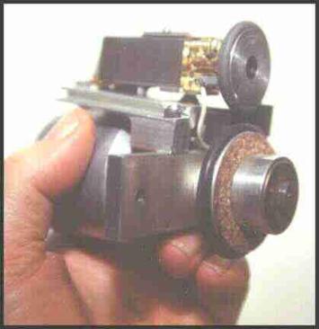
This photo shows an example of one I built some years ago for a 45 line camera, based on the Sanabria triple interlace format. The 10 inch scanning disk operates at 900 RPM. In the photo, I'm holding the assembly by the generator, on the shaft of which is part of the hub that supports the scanning disk.
The hub has a rubber tire mounted on its largest diameter, which is actually an "O" ring. Mounted on a platform above the generator, is a 12 volt permanent magnet DC motor, with a wheel and tire on its shaft.
The original purpose of this motor was to propel a "HO" scale model train. The DC motor is mounted on a hinged support at its rear .
At the front of the motor, a spring is used to keep the tire on motor wheel separated a short distance from the tire on the the hub. A small amount of pressure on the top of the DC motor will compress the spring and allow the two rubber tires to contact. Pressing on the DC motor also operates a micro switch located below the motor.
The power supply for this assembly consists of a 12 volt center tapped, 1 ampere filament transformer, with a full wave bridge rectifier connected across the 12 volt terminals. The AC generator is connected to the center tap and either of the 12 volt transformer terminals. The DC output of the bridge rectifier connects to the DC motor with the micro switch
mentioned earlier, connected in series with either of the motor leads.
With power applied to the transformer , the AC generator may hum, but doesn't run. Applying a downward pressure near the front of the DC motor puts the two tires in contact and closes the micro switch that turns on the DC motor. The DC motor brings the AC generator up to its operating speed of 900 RPM. Since the generator has 60 Hz power
applied, it tends to run only at 900 RPM. When the pressure is removed from the DC motor, the tires separate and it slows to a stop while the AC
generator now running as a motor continues to rotate at 900 RPM.
|
 |
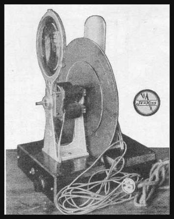
The second approach for driving the receiver scanning disk was one using two motors, with the second being a synchronizer or a phonic motor. All of these models used a variable speed motor and a secondary one to provide sync. Some manufacturers gave you a choice of the two types, such as the "Major" mentioned earlier and also the Jenkins Kits, which were sold in the United States. Jenkins kits, such as the one shown here to the right, provided your choice of one or the other. Some were shipped with both. The Hollis Baird kits (from Boston Mass.) were supplied with a phonic motor only (but they also offered a synchronous motor model too) and the Globe kit had a six pole synchronizer only.
The See-All kits appeared to be in many respects, copies of the Jenkins kits and came with a 6 pole synchronizer only. ICA produced a kit with an induction main motor and a synchronizer motor. All of the sets mentioned here used a rheostat type of speed control for the main motor.
Sync pulses were not required with phonic motors but synchronization could be further improved by causing the beginning of each scan line to be black for a short period of time. Mr. Baird used this method in his broadcasts from England. It worked by increasing the output of the filter that drove the phonic motor coils.
Comparing the performance between using a synchronizer or a phonic motor, usually comes out in favor of the synchronizer, partly because you have sync at all times, even without signal. In these times, with power
companies all tied together into a common grid, it is just the easiest way to go. Given a choice, the synchronizer if properly sized, will be the more effective of the two.
The closed loop servo type of motor control can be very successful and usually affords the lowest cost. Smaller DC motors are plentiful and generally cost very little. The same is true for the necessary electronics. The NBTV organization has published a number of proven circuits that are relatively simple and do in fact work quite well. These circuits add very little to the total cost. But as in all things, much will depend on how much you are able to do yourself. Unlike the phonic motor systems, the closed loop system will require a signal source that includes sync pulses in its output. Unless the pulses are available separately, any interruption in the picture signal will probably result in a loss of sync.
Peter Yanczer |
 |

All rights reserved. |
|