German Television on June 21, 1932!
By 1932, most television development activities in the United States, were now directed towards receivers using a cathode ray tube. This was also true in Great Britain but to a much lesser extent in Germany.
At the 1932 Berlin Radio Exhibition, in addition to radios, there were also displays and demonstrations of both mechanical and cathode ray tube television receivers. Telefuken demonstrated two sets, one was a 48 line mirror drum type, equipped with a Kerr Cell providing a 16" X 20" B/W picture. The pictures were judged to be very good, bright and with a slight amount of flicker. They also demonstrated a cathode ray tube set, providing images of 90 lines at 25 images per second. These images had a pale green color, measured 4.8" X 3.6" and were judged to be excellent.
Loewe demonstrated a 90 line cathode ray tube set, operating at 25 pictures per second. The images measured 4.8" X 3.6". In this case, the picture had a distinct blue color. Those who saw it, judged the picture to be very good to excellent.
Fernseh A.G. Their first of three entries was a 120 line at 25 frames per second, disk type receiver equipped with a new type of Sodium lamp. The 2.8" X 3.6" picture produced was a pale yellow color. They used a similar lamp with a 90 line disk type of receiver and it too was operating at 25 frames per second. The picture size on this second set was 6.4" X 4.8" and the picture quality on both was judged to be very good. A third working entry from Fernseh A.G., was a 90 line mirror screw operating at 25 frames per second, with an image size of 6.4" X 4.8". A neon lamp was used to illuminate the screw and the image was pink in color. The image detail was excellent, but the intensity was judged only as good.
There was also a fourth entry shown, but it was not working. It was a 90 line mirror screw exactly like their other, except that it was to be illuminated by a Sodium lamp.
H.H.I. (Heinrich Hertz Institute for Wave Propagation) demonstrated one 90 line mirror screw providing 25 frames per second. They used a new H.F. Mercury/Argon lamp that produced a blue picture measuring 5.2" X 6.0" and judged very good to excellent.
R.P.Z. (German Post Office) They demonstrated one cathode ray type receiver, another disk type with a sodium lamp and and a third using a mirror screw, also with a sodium lamp. All three provided 25 pictures per second. The picture on the cathode ray tube set was blue and it looked to be yellow on the other two. Picture quality on these three sets were judged to be very good.
TeKaDe Demonstrated three different size sets, all with 90 line mirror screws and using Neon lamps for illumination. The smallest set produced a 2.4" X 2.8" picture. The next was 5.2" X 6.0" and the largest was 12.0" X 14.4". All three provided 25 pink colored frames per second and were judged to be good to very good image quality.
There were no television sets offered for sale at the Berlin show for 1932.
Now, let's jump ahead two or three years, 1934-1935.
Problems noted in the 1932 report have for the most part addressed, solutions developed and incorporated. Picture colors are now a good B/W or at least nearly so. Synchronizing has improved and return beam blanking on cathode ray tubes has lead to much improved picture quality. Cathode ray tube life was greatly improved. With the exception of TeKaDe, all of the potential major television manufacturers have abandoned mechanical scanners of any sort. (It must be pointed out, that TeKaDe also has a major effort ongoing to develop television receivers using cathode ray tubes).
|
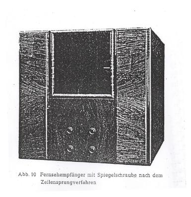 |
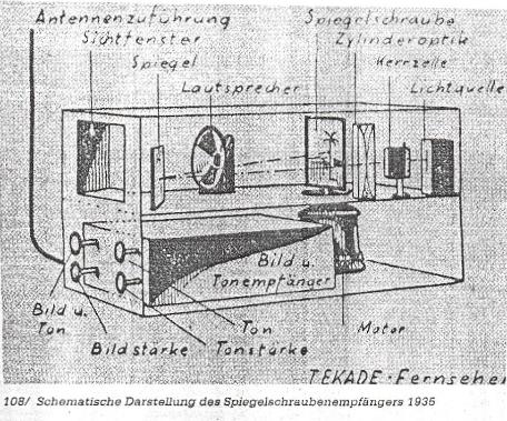
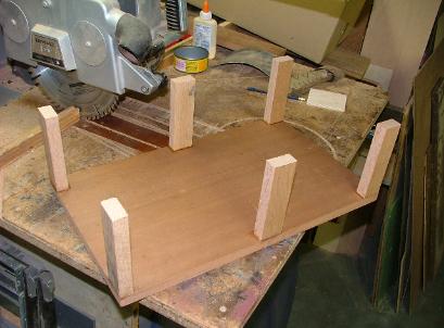
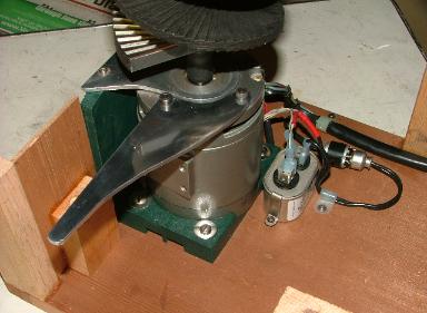
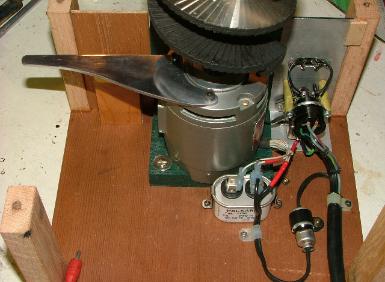
TeKaDe continues to engage in attempts to develop low cost mechanical television receivers and has released these two photos shown here and below, of a model for year 1935.
The photo here shows the complete receiver in its cabinet. It measures about 12 inches square and is about 18 inches deep. The cabinet is all wood except for the glass window on the front, through which one sees the television image. The shipping weight on this receiver is about 25 pounds.
The second photo shows approximately where some of the various significant parts are located. The drawing shows there is a support deck about center from top to bottom and from front to back, with the optical parts located above and the electrical parts mounted below. Since this drawing and its associated comments are written
in pencil, it must be assumed that this is not a "released" drawing and that the actual components and their placement may differ from
the actual finished or completed item. |