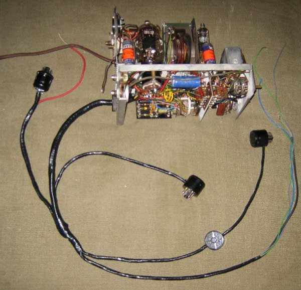
The connecting harness is missing. We have a photo we can use to
build a new one. The harness has a 12 conductor shielded cable, about 6
more conductors unshielded, and a two conductor line cord, plus three
thin pieces of wire in 1/8" diameter tubing. All of these are wrapped in
plastic tape.
We will use the shielding from a piece of RG8 coaxial cable to make a new
12 conductor shielded cable.
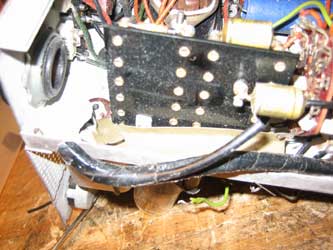
At the end of the harness are three octal plug/socket assemblies which
are plugged into tube sockets in the TV set, and the tubes are then
plugged into the top of the assemblies. We will break some octal tubes to
salvage the bases, wire the bases to the sockets and to the harness, put
the sockets in the top of the octal base, then hold the sockets in place
using set screws. A metal cap with an octal plug will be used for the
assembly that plugs into the horizontal output tube socket.
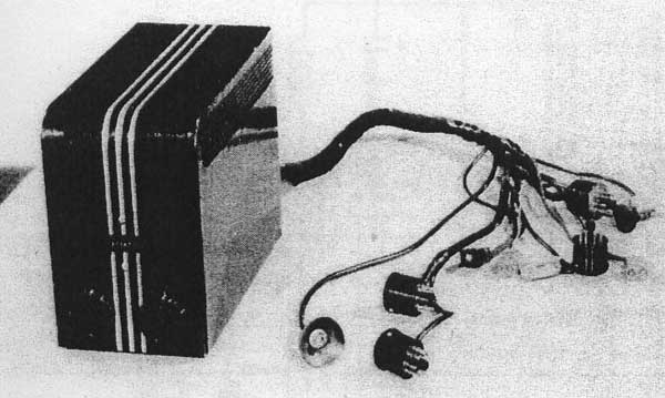
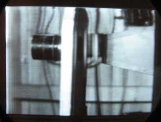
The harness, showing the plug/socket assemblies, the
HV connector, and various other connections
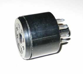
Cap for octal plug
The replica plug/socket assemby
The surviving portion of our harness
Start of the new harness. The shielded cable contains 10 conductors
for the vertical circuits. The black wire taped to the shielding is
one of 3 "low capacity" cables, which have an outside diameter of 1/8"
and contain a very thin (32 ga) wire.
Here is the completed harness. From lift to right are:
plug to go in 6BG6 horizontal output tube socket, low capacity wire to go
on pin 6 of the 6SN7 horizontal oscillator socket, plug/socket assembly
to go under 6W4 damper tube, plug/socket assembly to go under 6K6
vertical output tube, plug/socket assembly to go under 6SN7 vertical
oscillator tube, and wires to connect to the yoke.
Part of the harness, showing the plug/socket assemblies
for the vertical output and vertical oscillator tubes
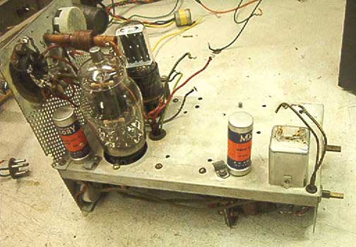
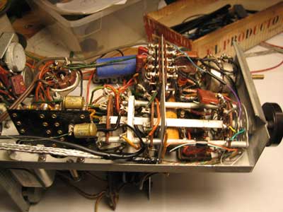
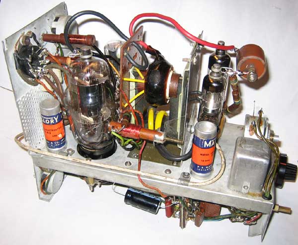
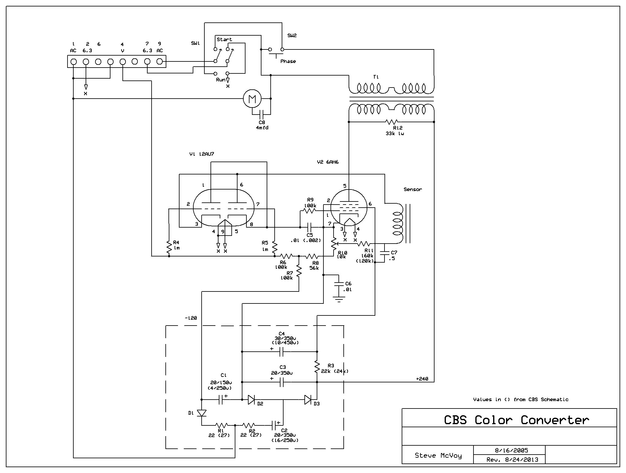
The circuitry has been restored, with new capacitors installed in
the old paper capacitor shells, and new electrolytic capacitors installed
inside the old shells.
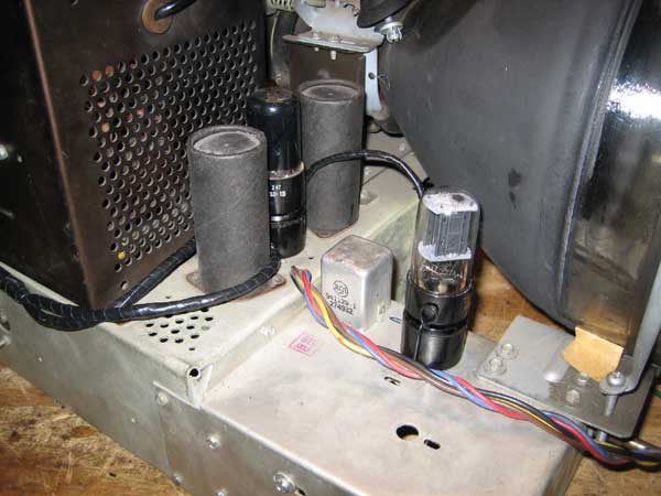
The flyback transformer and HV rectifier assemby are missing. We
don't have photos of what the original assembly looked like, so we will
have to improvise.
The flyback is also a problem, since it is designed to work at 29,160 Hz.
The issue is apparently the retrace time, which is determined by the
resonant frequency of the flyback. The resonant frequency was raised by
removing much of the secondary winding of the flyback, and using a
voltage doubler to get the 12 KV required for the CRT. We will install a
flyback from a 1949 RCA set, and experiment with removing
windings from the flyback until we get about 6 KV HV. We will then
connect the adaptor to the 9T-246 set, feed
the set field sequential video and observe the picture, looking for
evidence of horizontal retrace problems. If this works, we will add a second filament winding for the second HV rectifier, and build the voltage doubler.
We will also have to experiment with the secondary winding of the flyback.
The one originally used in the adaptor has 4 taps, which are used in
circuitry that sets the width of the picture in both color and monochrome
operation (In color, the picture is reduced to about 7" diagonal on the
ten inch screen. The replacement flyback has only 2 taps.
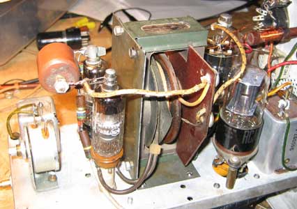
Here is the RCA flyback installed in the adaptor
The voltage doubler, with the RCA flyback
I finally got the adaptor to work fairly well using this flyback. There
are several errors in the CBS schematic that I found out by trial and
error. In the color mode, the flyback produces only 6 KV of high voltage
using a single rectifier. I have now installed a voltage doubler, which
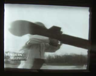
produces about 9.5 KV. Here are photos off the screen:
You can see retrace problems in the picture on the left (white band) due
to the flyback having too low a resonant frequency. Because we only have
9.5 KV from the doubler, we can't remove any turns from the flyback to
try to solve the retrace problem. We will try the following to increase
the voltage: 1) replace the coupling resistors used in the doubler with a
high voltage diode. 2) replace the 1X2 rectifiers with diodes (eliminates
the load of the two filaments). 3) Use a solid state tripler unit fed off
the plate of the horizontal output tube 4) Try a similar flyback that is
designed to be used with a voltage doubler.
If we can get sufficient high voltage to remove turns from the secondary,
we will do so to see if the retrace problem is solved. If not, we will
have to be satisfied with the results we have. The picture is probably
acceptable as it is.
We replaced the flyback with a FLY-4, which is a Thordarson replacement
for one used in 1949 RCA sets with the 16AP4 CRT. This flyback is
designed to operate with a voltage doubler. The results were a dramatic
improvement over the 9-T-246 flyback. The only problem was how to reduce
the width of the picture without reducing the high voltage. We
accomplished this by adding an inductor and resistor in series with the
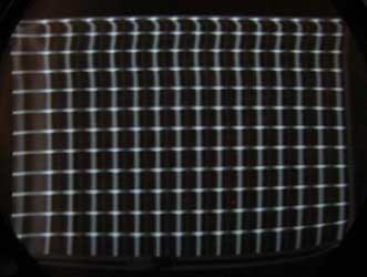
yoke. In the photos below you can see that the retrace artifacts are
almost invisible. The only problem shows up in the crosshatch pattern,
which shows that the far left side of the screen is very nonlinear. I
don't think this will be very visible in most scenes.
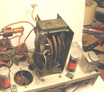
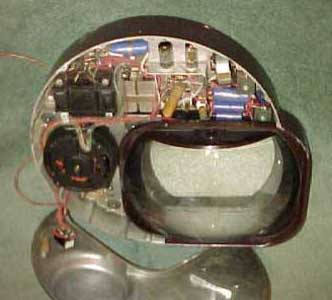
The top of the completed adaptor, with the FLY-4 flyback, HV
doubler
rectifier, and vertical linearity control (far right). In front of the
flyback is the inductor and resistor used to reduce the width in the
color mode. At the upper left is the 11 pin socket for the converter,
which houses the color wheel and control circuitry.
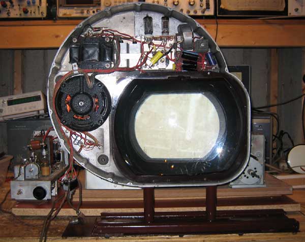
The converter, mounted on its sliding track, in front
of the RCA 9-T-246 receiver (out of the cabinet). The adaptor can be
seen on the left. All we need now is the color wheel to complete the
restoration
The mounting track is missing. We have made a replica using a
slide assemble from a cabinet drawer.
The motor needs to be taken out, lubricated, and made to work
again. After lubricating it, the motor works well.
The color wheel is missing. A replica will have to be made from
the engineering drawings and photos we have. John Folsom has built a
wheel, and suggested some color filter sheets that should come close to
matching the ones CBS used. I will have two 1/16 inch thick 15 1/2 inch
diameter clear plastic disks made by a sign company, then cut out the
filter material and sandwich it in between the two disks. Then I'll seal
the edge with tape.
The new wheel is complete (see below), and when I
installed it, the converter worked and displayed good color pictures. The
remaining problem is that the saturation of the green and blue are not
good, and I'll have to experiment with different filter materials.
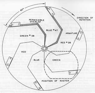
A CBS drawing of the wheel
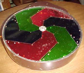
The color wheel out of the other surviving
converter
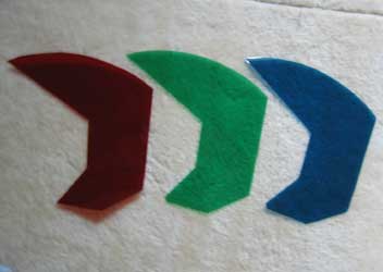
Filter segments, cut out of thin
stock
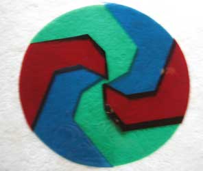
The filter segments, laid out as they
will be on the wheel
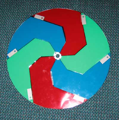
The completed wheel, with metal strips installed for the
synchronizing magneto. The thin filter material is sandwiched between two
1/32 inch thick clear plastic disks
The circuitry has been restored, with paper capacitors and
electrolytics stuffed with new ones. The control circuitry appears to
work properly.
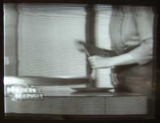
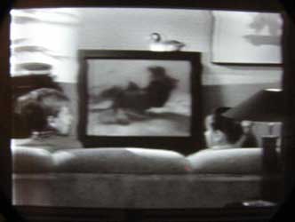
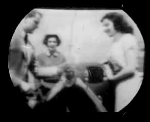
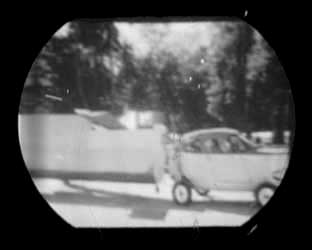
Photos off the screen of the converter,
before installation of the color wheel. The actual picture looks quite a
bit better
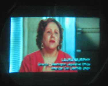
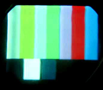
These are photos of the screen with the color wheel
installed. Notice how weak the green is. The blue is also not fully
saturated. I need to experiment with different filter materials. Also,
notice the poor resolution in the lettering. The CBS system was limited to
about 240 lines of horizontal resolution.
The magnifying lens is badly scratched. I used a kit to remove
scratches. It
consists of various grades of emery cloth and a bottle of liquid abrasive.
I used the 1500 grit to remove the deep gouges, then went over all the
scratches with 4000 until they all disappeared. Then I used the liquid
abrasive to do the final polishing. The whole process took about 1/2 hour
and the lens looks like new.

