
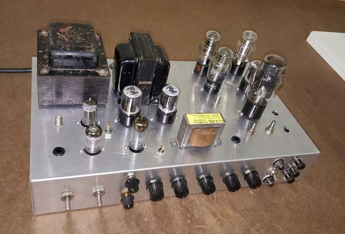
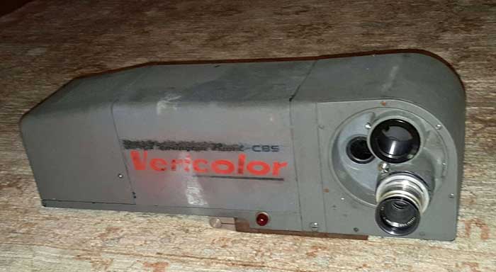
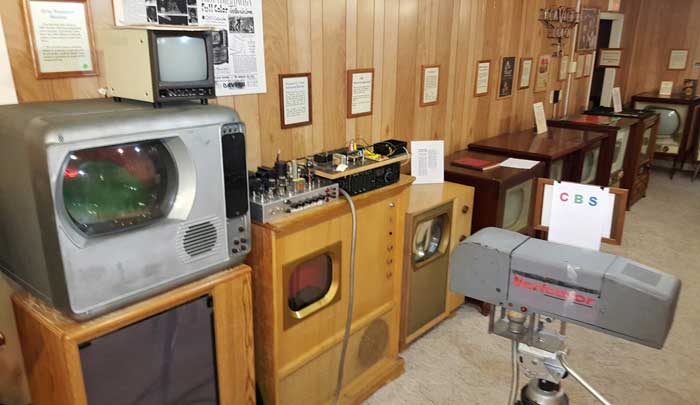
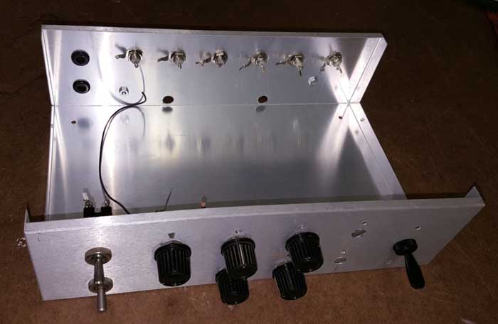
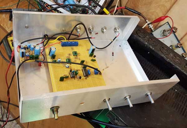
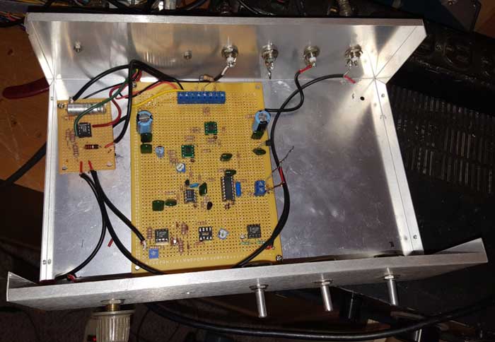
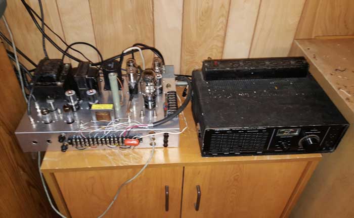
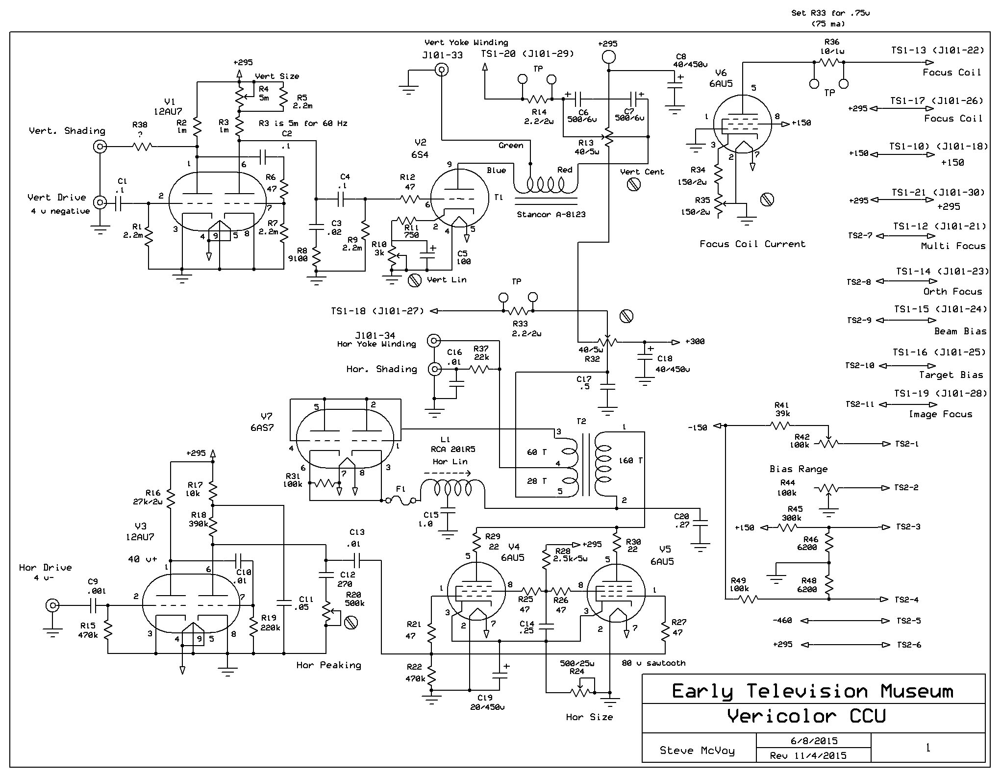
Early Color Television Remington-Rand Vericolor Camera RestorationOur goal is to get this camera working for the 2016 Early Television Convention. There are several steps: 1. Design and build a Camera Control Unit. We have complete documentation from CBS on the original one. 2. We have an old CBS color bar generator board we made years ago. We will use this as a sync generator. 3. Rebuild the electronic circuits in the camera head 4. Make a custom cable to connect the camera head to the CCU. The camera uses a connector which we will not be able to find. 5. Construct or find a suitable tripod. We plan to get it working in stages: 1. Using NTSC scan rates, get the IO to produce a picture (black and white, no color drum rotation) 2. Change to CBS scan rates, get a black and white picture 3. Full CBS color. Our progress is described here: June 18, 2015 CCU: We will copy the circuits from the original CCU for horizontal and vertical sweep and for the various voltages needed by the camera head. These will be vacuum tube circuits. We will design new regulated power supplies for +150, +300 and -150 volts, using solid state rectifiers. The new CCU will be built on a 10 x 17 x 3 inch aluminum chassis, with the operator controls on one side. Eventually we will put a front panel on it and put it in an enclosure.
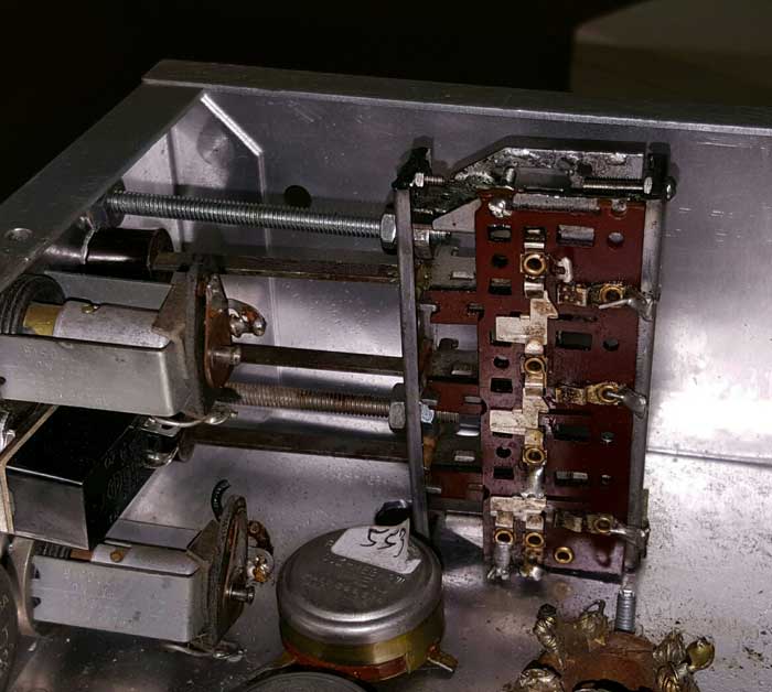
Controls (L to R): power, drum motor power, hor and vert size (top and bottom), beam, orth focus, target, image focus, multi focus, optical focus (toggle switch with indicator lamps) and lens select (3 pushbuttons) Most of the parts are easy to find. Some are more difficult, including the horizontal and vertical output transformers, the horizontal linearity inductor, and the lens turret control pushbutton switch. Fortunately, the documentation gives RCA part numbers for the vertical transformer and the linearity inductor, and we have found these parts. We have made a switch for the lens turret control from an old radio station selector assembly.
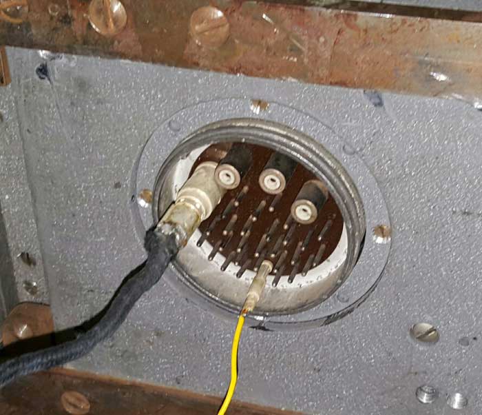
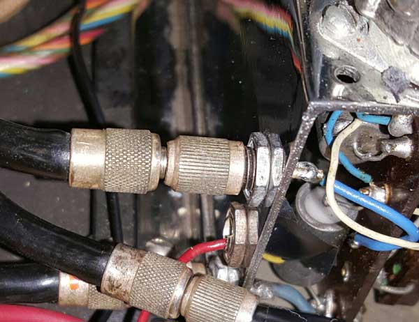
For the horizontal transformer, there are two options. First, the one used in the RCA TK-30 camera might work. We have a camera we can borrow one from, and we will try this first. The second option is to have a custom transformer wound. Fortunately, we have the original specifications for this, and we have asked Heyboer Transformer if they can build one. Cable: We have a cable used in late 40s RCA cameras. It has 3 coax cables plus about 20 wires in it. Our camera requires 4 coax cables and about 15 wires. Our plan is to use the cable we have with the RCA connector shell (which mates with the CBS camera connector). The 3 coax lines in the cable will be soldered to the sockets we salvage from the RCA connector. The individual wires in the cable will be soldered to pins we salvage from the RCA connector. These will be plugged in to the camera connector individually, and the shell will be put over them.
Pins and coax put directly on the camera connector
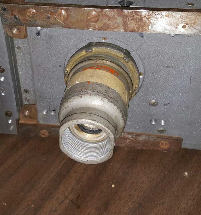
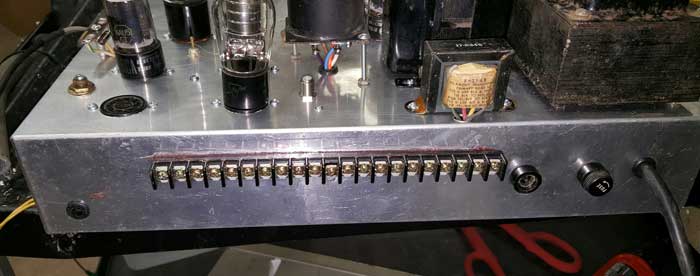
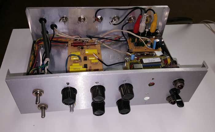
The RCA shell over the connector. The cable will come out the back of the shell. The problem is the 4th coax, which the RCA cable doesn't have. The CBS camera uses the 4 coax cables for horizontal sweep, vertical sweep, video output and blanking input from the CCU. We will use the 3 coax cables in the RCA bundle for the first 3, and attempt to use a regular wire for the blanking, which is low level (4 volts) and relatively low fequency (29 kHz square wave). CCU: Construction is almost complete. I have decided to mount a screw terminal strip on the rear of the chassis to connect the camera cable. This will allow the CCU to be disconnected from the camera. I found a horizontal output transformer from a RCA TK-31 camera, which I have temporarily mounted on the chassis. If it works I'll attach it permanently.
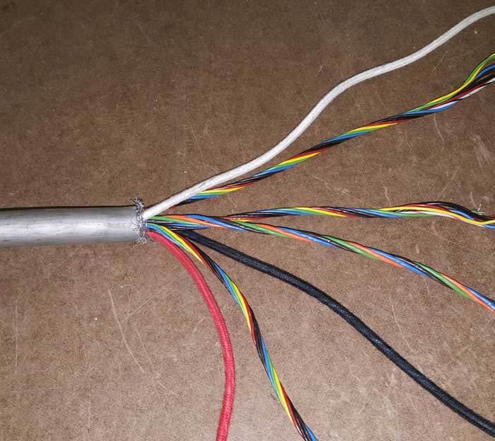
I am still missing connectors for the three test points and a momentary SPDT toggle switch for the optical focus. Otherwise I have all the parts. June 22, 2015 CCU: Today I completed wiring and fired it up. First task was to determine the value of the dropping resistor in the +300 supply. Then I connected H and V drive signals from a NTSC sync generator. I found a couple of wiring mistakes, then I got reasonable waveforms on the H and V yoke connections (no camera connected). Next I need to find a video monitor so I can connect the camera and try to get an image on from the IO. Cable: I cut a 25 ft section of a spare RCA camera cable and removed the shield:
The wires are bundled. One of the bundles has larger wire sizes than the other - I'll use that for the AC to the motors and IO filament transformer. I will then chose the bundle that is farthest away from the AC bundle for the blanking line.
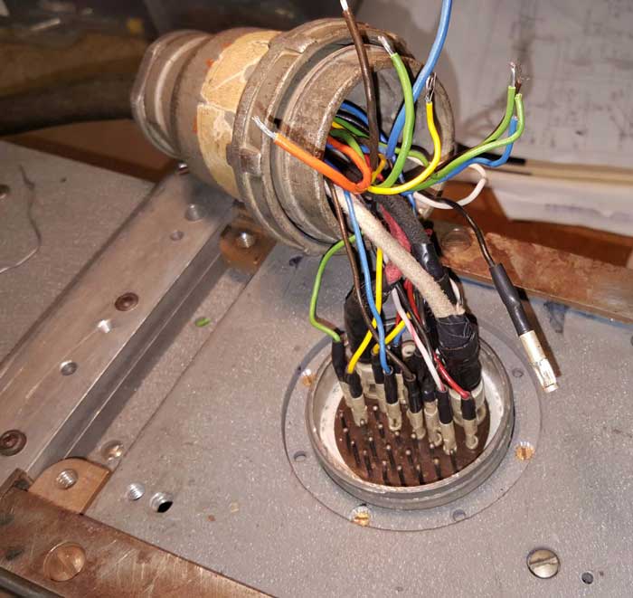
Pins on the connector. Once the remaining pins are installed I will put the shell in place. June 25, 2015 Today I completed the cable and connected it to the camera. I then fired it up. All the tubes in the camera light. Unfortunately, an electrolytic capacitor exploded, so my next step will be recapping the camera. I did verify that I have the proper focus voltages and current through the focus coil. The vertical sweep waveform to the yoke looks normal, but something is strange about the horizontal waveforn. Disconnecting the line to the yoke makes no difference in the waveform, and you would think that removing the load would change the waveform. I'm leaving for Colorado for a month, so this is as far as I will get until I get back.
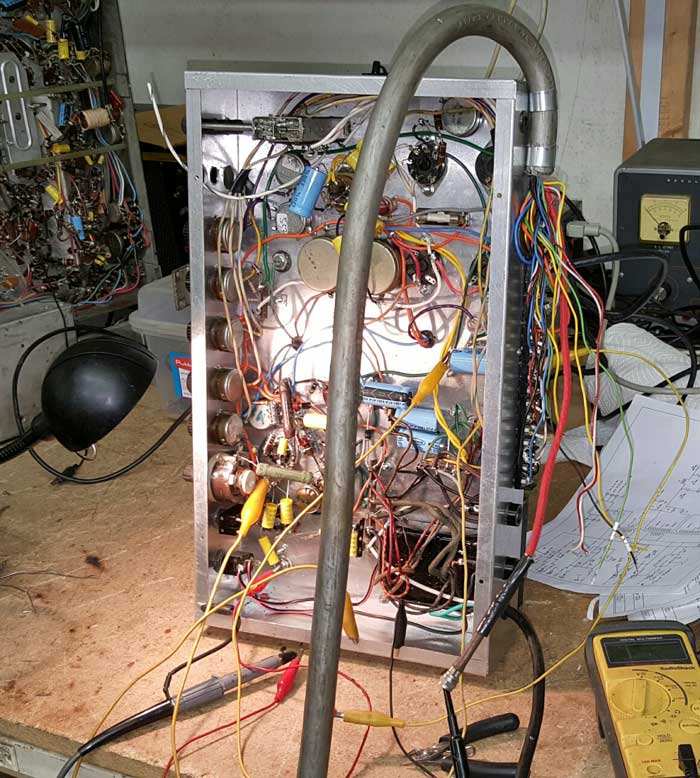
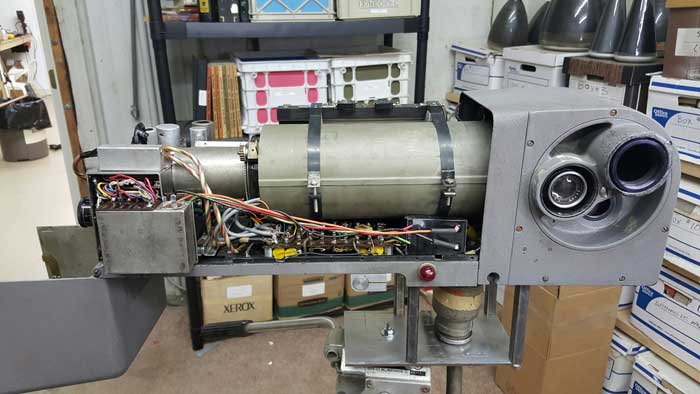
July 23, 2015 I'm back in Ohio now, and had a couple of hours to work on the camera. I removed the IO tube and yoke and discovered a mess underneath. Wires cut, some resoldered so poorly that adjacent pins on the terminal strip might short. I documented the connections to the tube and cleaned up the wiring. There was even an electrolytic someone had added that had both the + and - leads connected to ground. Now I get the proper resistance across the horizontal and vertical yoke windings at the CCU, but I read a dead short from the center pin to ground of both the horizontal and vertical yoke coax lines from the CCU to the camera. I had time to determine that the shorts weren't in the wiring from the CCU to the camera, but in the wiring from the terminal strip in the camera to the IO yoke. Tomorrow I'll try to figure it out. Once that is fixed I'll replace the electrolytics in the camera and check continue checking the other circuits. July 24, 2015 Today I found the problem with the shorted yoke connections. There are short miniature coax cables from the terminal strip in the camera to the yoke. The insulation had deteriorated, so I replaced them. That solved the problem:
Next I turned on the power and measured the voltage from the 1600v RF supply in the camera. It was only 140 volts. I removed the stainless steel chassis at the rear of the camera that contains the video preamplifier and the RF power supply:
The stainless steel chassis wirth the video preamp (left) and the RF power supply (right, removed from the chassis)
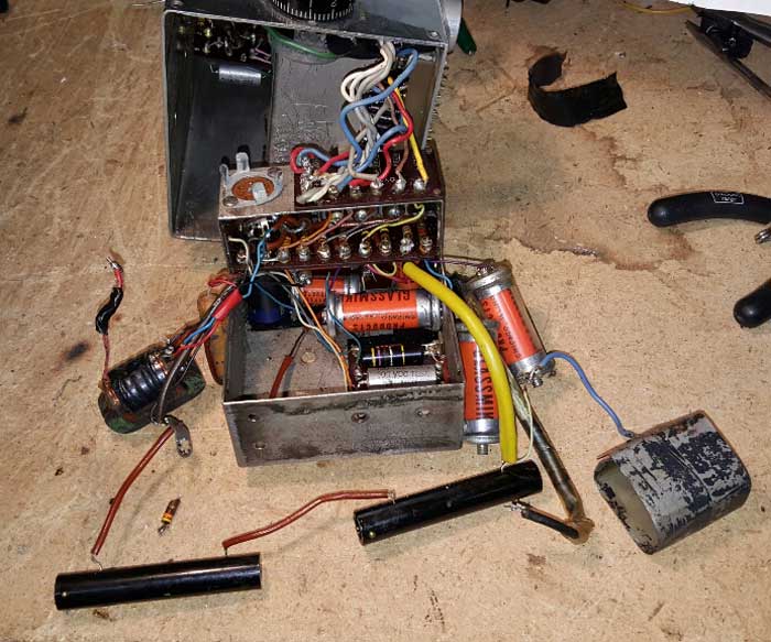
The interior of the RF power supply
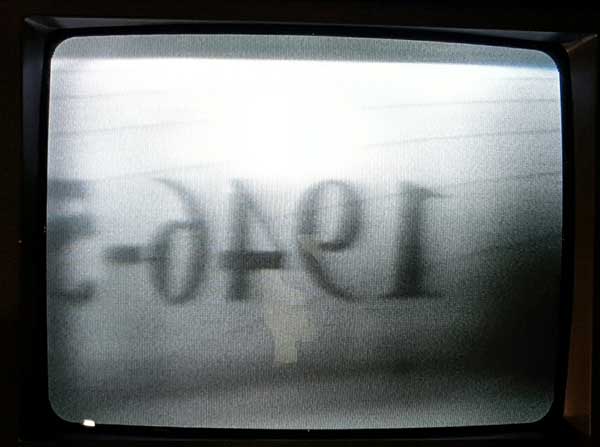
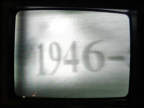
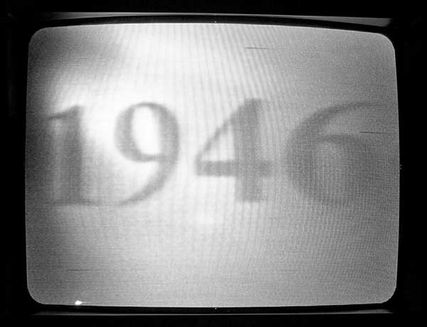
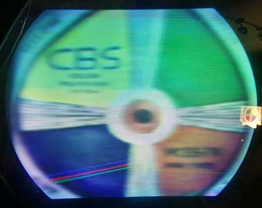
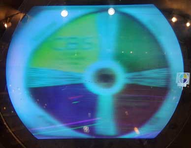
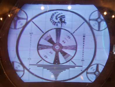
With the loose components removded. The tubular black things are selenium rectifiers. The oscillator transformer is on the left. I will replace all the paper capacitors and the selenium rectifiers. Most likely that will fix it. August 14, 2015 Finally able to return to the project. The 1500 volt power supply wouldn't provide the required voltage, no matter what parts I replaced. I've concluded that the transformer has a short between windings and I've sent it to Heyboer to be rewound. To keep the project going I've buit an external temporary power supply and connected it to the camera. I now have the proper voltages on the dynodes. Next is to recap the video preamplifier and test it. I will also verify that I have the right voltages on each pin of the 5820. August 17, 2015 I replaced the electrolytics in the video amp. The other caps seem OK. I built an external 1500 volt supply and connected it. I checked all the voltages on the IO socket and front ring and they are correct. I fired it up and found that there is a short from the center conductor to ground of the coax carrying the blanking input to the video amp chassis. For now I'm ignoring it and will fix it later. After much experimentation with the 6 5820s we have I finally found one that produces a poor quality picture. I am using NTSC scan rates for now. I have the following problems that the picture revealed: 1. The horizontal sweep is reversed. That is explained by the fact that I used a horizontal output transformer that is different from the one in the Rand CCU. 2. There is significant overscan in the vertical. That may be because the circuit (from the Rand CCU) is designed for 144 cps vertical rate. 3. The video preamp only puts out about .3 v. I need a video amplifier. 4. My sync combiner circuit is crude. I need a good combiner. 5. I think the one working 5820 I have is tired. I need to get a couple of good ones. August 18, 2015 Here is a photo off the screen. I've improved the sync combiner and am using a modulator with a variable video modulation, so that the .3 v video has some contrast. I also reduced the vertical scan so that it is about right for the IO. The retrace lines are because the blanking circuit in the IO is disconnected until I get a pulse to input that is the proper polarity. As you can see, there is much to be done to improve the picture. The main problem is my 5820. I will go through all our cameras and remove the tubes. We should have lots of them, and one or more will probably be good. August 19, 2015 I found a much better 5820 today. Reversed the wires on the horizontal output transformer, and made changes in the power supply to assure good 300v regulation. Picture is much better, though the photo doesn't really do it justice. There are linearity problems, but I won't deal with that until I go to the CBS scan rates. The picture is noisy, and has some sort of beat pattern in it. Not sure where that is coming from.
Cliff benham is making a video amp/sync inserter for me, along with a monochrome monitor for the CBS scanning rates. Once I have them, I'll build a crude sync generator for the CBS scan rates. August 20, 2015 Today I built an inverter to take the negative going blanking signal from the sync generator and produce positive going pulses for the camera. Adding retrace to the IO improved the shading of the picture and eliminated the retrace lines. I then worked on the motor that adjusts the optical focus. Applying 120 vac wouldn't make the motor operate. I took off the gear reduction part and the motor would turn, but had to be started by hand. I noticed on the schematic that there are two 22 mfd electrolyitics back to back across the motor. However, I couldn't find them in the camera. Attaching capacitors made the motor work, so my assumption is that the capacitors were in the CCU and that the schematic was wrong. I installed them in the camera, however, since that is what the schematic shows..
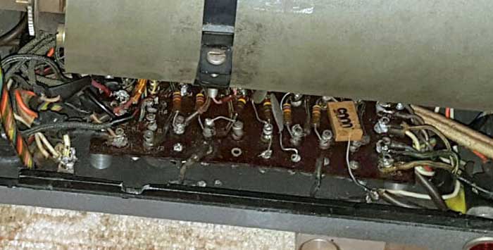
While looking for the electrolytics I decided to replace all the capacitors in the camera. They are located on the bottom of the terminal strip, and were difficult to replace:
Tomorrow I'll work on the motorized lens turret. August 21, 2015 Today I checked the resistors and capacitors in the video preamp. I discovered that it had been modified - someone had added a 1k resistor in series with the 180 ohm cathode resistor in the first amplifier section. I removed it, and the video gain is much higher. I can now get 1 v pp out of the preamp. Next I worked on the color wheel motor. The motor leads had been cut. I determined how to reconnect it. The 1.5 mfd capacitor was missing, and I can't see where it was located. I will add a terminal strip to mount it. For now it is connected with clip leads. The motor works fine.
Finally, I tested the lens turret motor. It works well, though some adjustment of the stopping point for each lens is required. We only have one lens for the camera. Each lens has a different mounting style, so I'll have to find the right style of lens for the two missing ones. August 22, 2015 Today I added test points for the horizontal and vertical yoke signals and the focus current to the CCU. I also wired the wheel motor and capacitor:
I discovered a short in the cable from the CCU to the camera for the blanking signal. I'll have to take apart the connector on the bottom of the camera to see what is going on. Larry is in the process of removing all the 5820s we have in cameras on display. I hope one of them is good. Next step is to make a 29 kHz pulse generator to see how well the horizontal sweep works at that frequency. When Cliff finishes the CBS standard B & W monitor I'll be ready to try the camera at CBS scan rates. August 27, 2015 I took apart the connector and found the problem with the blanking line. Too much solder on the connector, which shorted to the coax ground. Now I need a replacement mini coax connector (chassis mounted part). If you have one, please let me know:
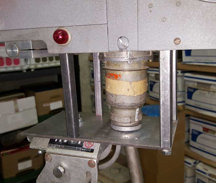
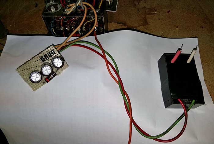
I designed a mount to mate the camera to a tripod. It is easy to make, and I should be able to get it done tomorrow. Heyboer can't rewind the transformer in the 1500 v power supply. They can make a new one, but is is much larger, and won't fit in the camera. I've decided to use is a Pico minature 1500 v supply inside the original HV chassis. I will use the 6.3 v filament line to create 6 vdc to drive it. Now I'm ready to try the camera at CBS scan rates. Cliff Benham has modified a small B & W monitor for CBS rates and has shipped it to us. I was going to make some pulse generators for the H and V rates, but Cliff reminded me that the color bar generator we made years ago (which made possible the first operational CBS sets since 1951) had separate sync and video outputs. He is making a sync splitter to create the H and V drive signals I need. He is also making a video amp/sync combiner. When all this gets here I can see how well the camera works at the CBS scan rates. I don't expect any problem with the vertical scan (144 Hz vs 60 Hz) since the circuit I used is copied from the Vericolor CCU documentation, and the vertical output transformer is the one called for. The horizontal scan (29,160 Hz vs 15,750 Hz) may be a problem. I am using the circuit from the Vericolor CCU documentation, but the horizontal output transformer is from a RCA TK-30, while the Vericolor schematic calls for a custom made transformer. 8/28/2015 Today I made an adaptor to put the camera on a tripod:
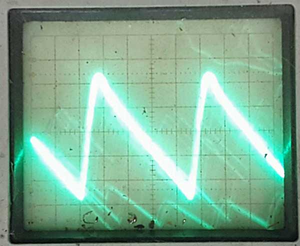
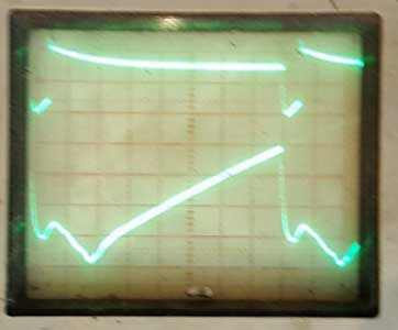
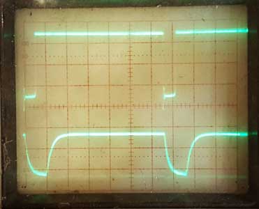
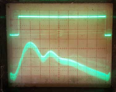
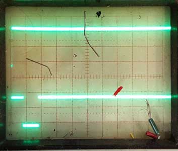
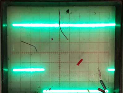
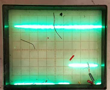
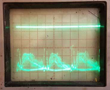
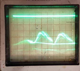
August 29, 2015 The CBS standard monitor arrived from Cliff Benham today. I connected the sync output of the CBS color bar generator to the horizontal drive input of the CCU. Here is the waveform I got on the horizontal yoke test point:
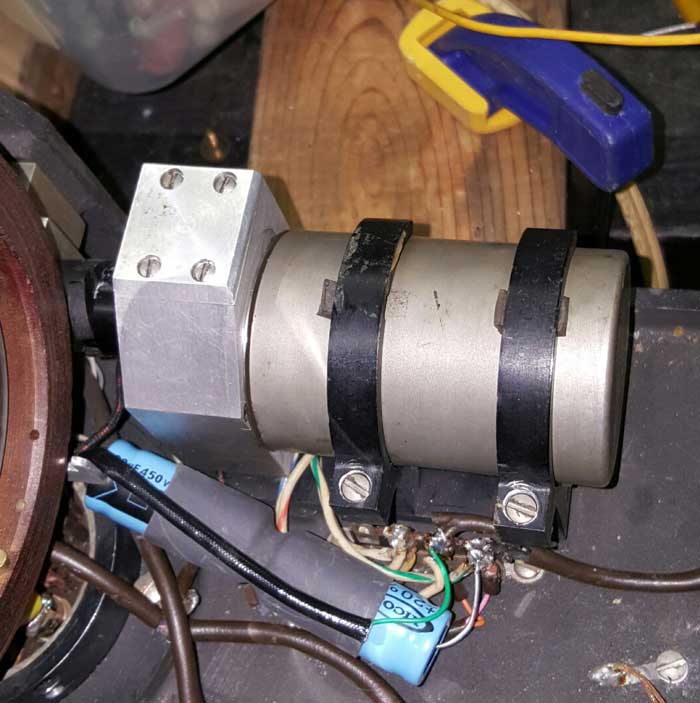
The linearity is much better than when the CCU was operating on 15,750 Hz, and the amplitude of this waveform is sufficient. There should be no issue with the horizontal scanning. Chuck Azzalina told me of his use of a EMCO E101 HV module to power the high voltage in 7 inch TV sets. This module can produce up to 10 kv dc and is small enough to fit in the space occupied by the original HV supply in the camera. I was concerned that the module wouldn't provide enough current at 1500 volts, but Chuck tested it, and it will work fine. He has built a DC supply that operates from the 6.3v filament line. About 2.7 vdc is required to provide an output of 1500 volts. Chuck has generously sent us a module and the DC supply for it. He also sent a replacement SMC chassis mounted connector for the video amplifier. Tomorrow I plan to build a simple vertical sync extractor to derive the 144 Hz signal for the vertical sweep. Then I'll be ready to look at pictures at CBS scanning rates. August 30, 2015 Today I built a sync separator. I also modified the monitor that Cliff Benham sent to work at CBS scan rates. Everything went well with that except that I don't have sufficient width. Not really an issue for now. I connected the sync separator to the CCU and fired up the camera. I heard an arcing noise and smelled something bad. A terminal strip that had the plates of the horizontal output tubes was arcing to the chassis. Apparently the move to 29 kHz made it happen. I got far enough to see a picture and to determine that both the horizontal and vertical sweeps are linear and have sufficient amplitude. The picture is terrible - because of limitations with my sync separator. The vertical part works fine, but the horizontal pulse is messed up during the retrace. The second problem is that I don't really have blanking for the IO tube. I inverted the composite sync (the camera needs positive going pulses) and used that for blanking, but it wasn't very effective. Cliff is making a sync separator that will solve the problem. There may be a problem with the power supply module that Chuck Azzalina is sending. The spec sheet isn't clear about how much output current is available when you run the supply below its maximum output (10 kv). It may be that the module won't have enough current capacity to drive the resistor divider network in the camera. If it doesn't I'll try increasing the value of the resistors in the divider to reduce the load. September 1, 2015 As I feared, the module doesn't have the current capacity to deliver 1500 volts into a 2.2 meg load. I modified the resistor divider network by increasing the value of each resistor by a factor of 2.2. That made the total load resistance about 4.8 megs. I was worried that there might be some current draw by the dynodes that would result in the divider not delivering the proper voltages. However, the voltages turned out to be fine. I built a DC power supply that uses the 6.3 volt filament line to generate about 7 vdc. That board was small enough to fit in the housing that contains the original power supply. There wasn't room for the HV power module, so I located it in front of the terminal strip in the camera.
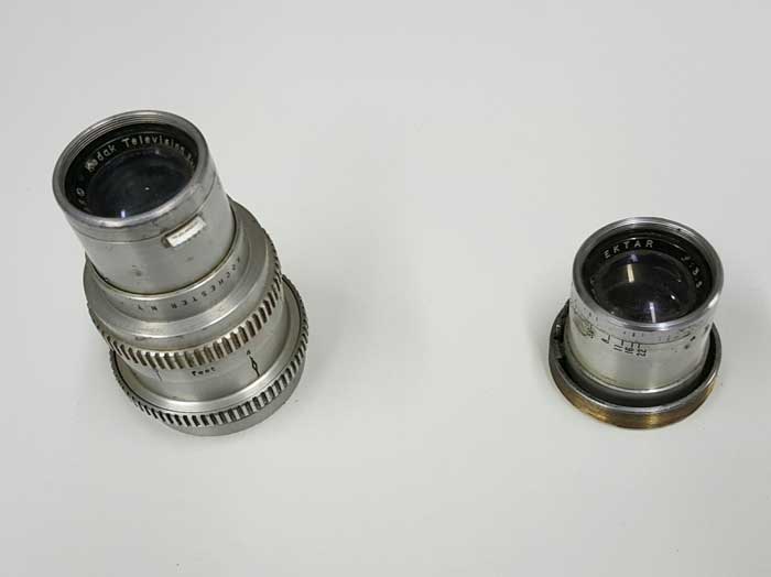
The next problem is the lens. The distance from the recessed mounting ring on the Vericolor camera is 80 mm from the IO face (that is the closest point - the IO tube can be moved farther away using the motorized mechanical focus). This is because the lens focuses on a 45 degree mirror inside the color drum, and then on the IO face. The other mounts are 130 and 145 mm from the face of the IO.
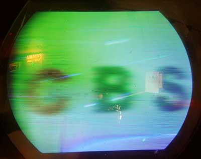
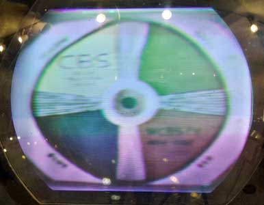
I checked a bunch of lenses from various cameras. I placed a lamp 6 feet from the lens and placed a piece of paper behind the lens at the point where the lamp image was in focus. For most lenses that point was 30 mm behind the mounting ring. A few lenses focused at 40 mm, and two at 55 mm. I think that indicates that the camera had custom made lenses. Several of my lenses have the first lens element recessed quite a way from the mounting ring. I could cut the tubing back and put a new mount. One of the lenses that focuses at 55 mm could be cut back so that it focused at about 85 mm, which would work for the camera. I found a 90 mm lens that had the rear element way up in the tube, and cut the lens off just behind it. I then wrapped it in tape and shoved it in one of the mounts. Works OK: Before and after September 2, 2015 Here are some pictures from the monitor screen:
The picture on the left is of a Sams Photofact front page. The one on the right is of two pieces of black electrical tape on a white background. You can see in both pictures that the horizontal resolution is bad. Looking at the images above at NTSC rates, I don't see that poor resolution. I noticed that changing the blanking signal made a big difference, so I suspect that the problem is in my blanking genertor. In fact, I don't have one - I'm feeding the composite sync signal to the blanking input. I think this is as far as I can go until I get a real sync/blanking generator from Cliff. September 3, 2015 While waiting for the sync separator to arrive, I've turned my attention to the color drum motor. I measured the current and found that it draws about 100 ma, or about 12 watts. It is a synchronous motor that turns at 1800 rpm at 60 Hz and 1440 rpm at 48 Hz. There are 6 color segments (one for each field in the frame). The motor needs to be run off a 48 Hz source that is locked to the vertical field rate, which is 144 Hz. The phase has to be adjustable to position the filter in front of the IO tube. Here is my initial idea of how to do this:
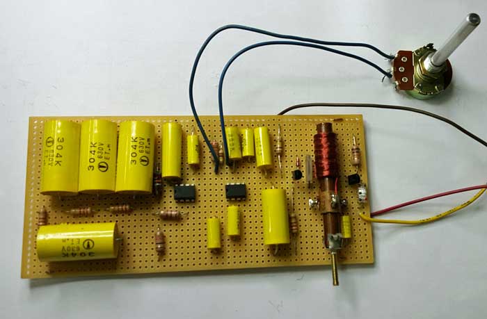
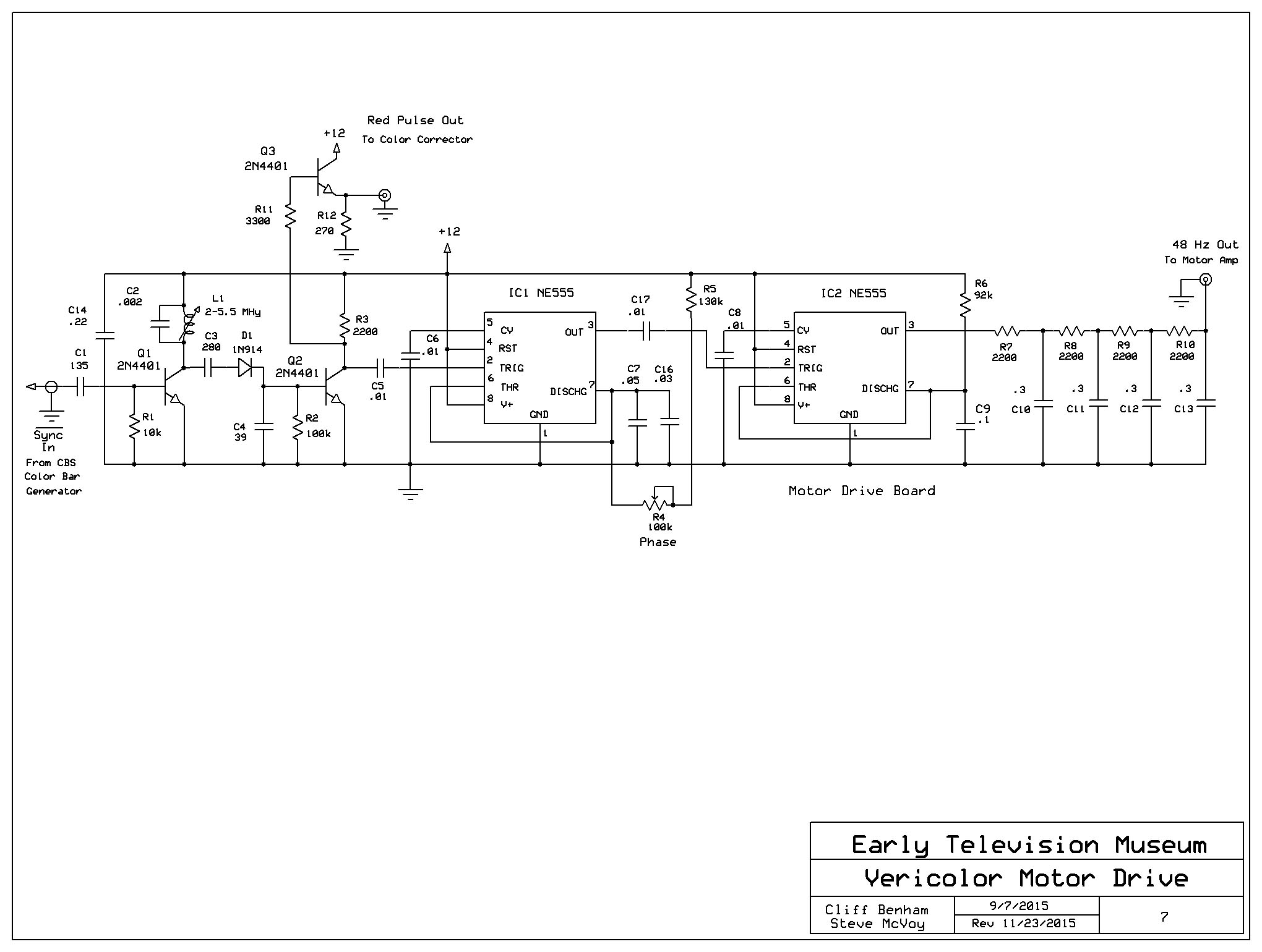
I'd appreciate comments and suggestions. September 5, 2015 Cliff Benham had a better approach for the motor drive. His design uses a red pulse extractor (there is a pulse every red field in the blanking inverval) to drive a NE 555 to create a 48 Hz square wave. Then a filter to turn it into a sine wave, followed by a power amplifier. I built his circuit and only got a red pulse every 6 fields. That may be a mistake I made in programming the eprom in the color bar generator, or may be something wrong in the circuit I built. I cleanup up my horizontal pulse extractor circuit and it improved the picture from the camera. Here it is now: September 7, 2015 By using the blanking output of the CBS color bar generator I was able to use Cliff's circuit to extract a pulse every red field. I modified his approach somewhat (schematic), by adding a NE 555 timer after the pulse detector to adjust the phase of the sine wave, which is required to synchronize the red filter on the motor drum to the red field video. The NE 555 is triggered by the output of the pulse detetor (Q1 and Q2), which is a very narrow negative going pulse. That triggers IC1 to go positive for a time determined by the timing components (R4, R5, C7). The trailing edge triggers the second timer (IC2), which goes positive for half a cycle at 48 Hz. By adjusting the R4 on IC1 the 48 Hz output is shifted, thereby adusting its phase relative to the red sync pulse. After IC2 is a filter to turn the square wave into something like a sine wave, whichj will feed an audio amplifier module. The module will be connected to the secondary of a 24 volt filament transformer, which will produe 120 vac for the motor. Cliff Benham is making this for us. September 10, 2015 Today I put the motor drive circuit on a project board and optimized the timing components. Here it is:
Also Cliff's sync separator arrived. Here it is:
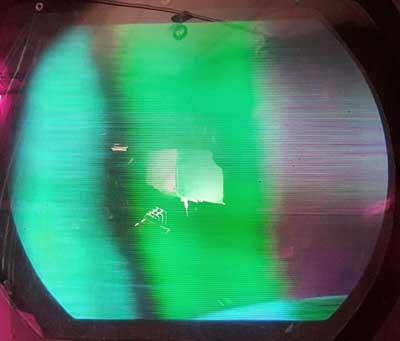
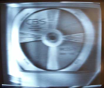
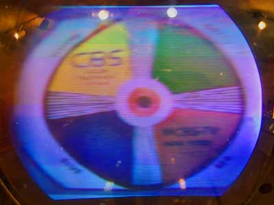
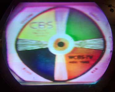
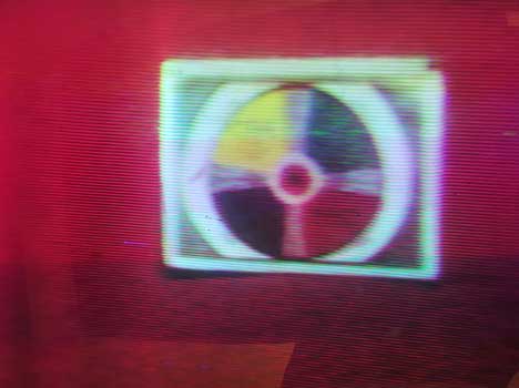
I now have everything I need to try CBS color from the camera. First will be to test the motor sync and phase. I'll use an old audio amplifier I have to drive the motor (to be replaced by one being made by Cliff). My plan is to use a piece of red paper in front of the camera. I will then sync the scope to the red pulse (from the motor drive board) and look at the video. I should be able to adjust the phase control on the motor drive to produce a waveform with high video level on the first field, then low video levels on the next two fields. If that works, I'm ready to hook the camera up to the Gray Research monitor. September 12, 2015 I connected the output of the motor drive board to an audio amplifier, then to a 24 v filament transformer backward. It was easy to get about 100 vac out of it to drive the motor (the motor seemed to run fine at that voltage, so I didn't increase it to 120 vac). I then moved the whole mess to the interior of the museum. After much messing around, I was able to get a crude color picture on the Gray monitor.
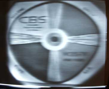
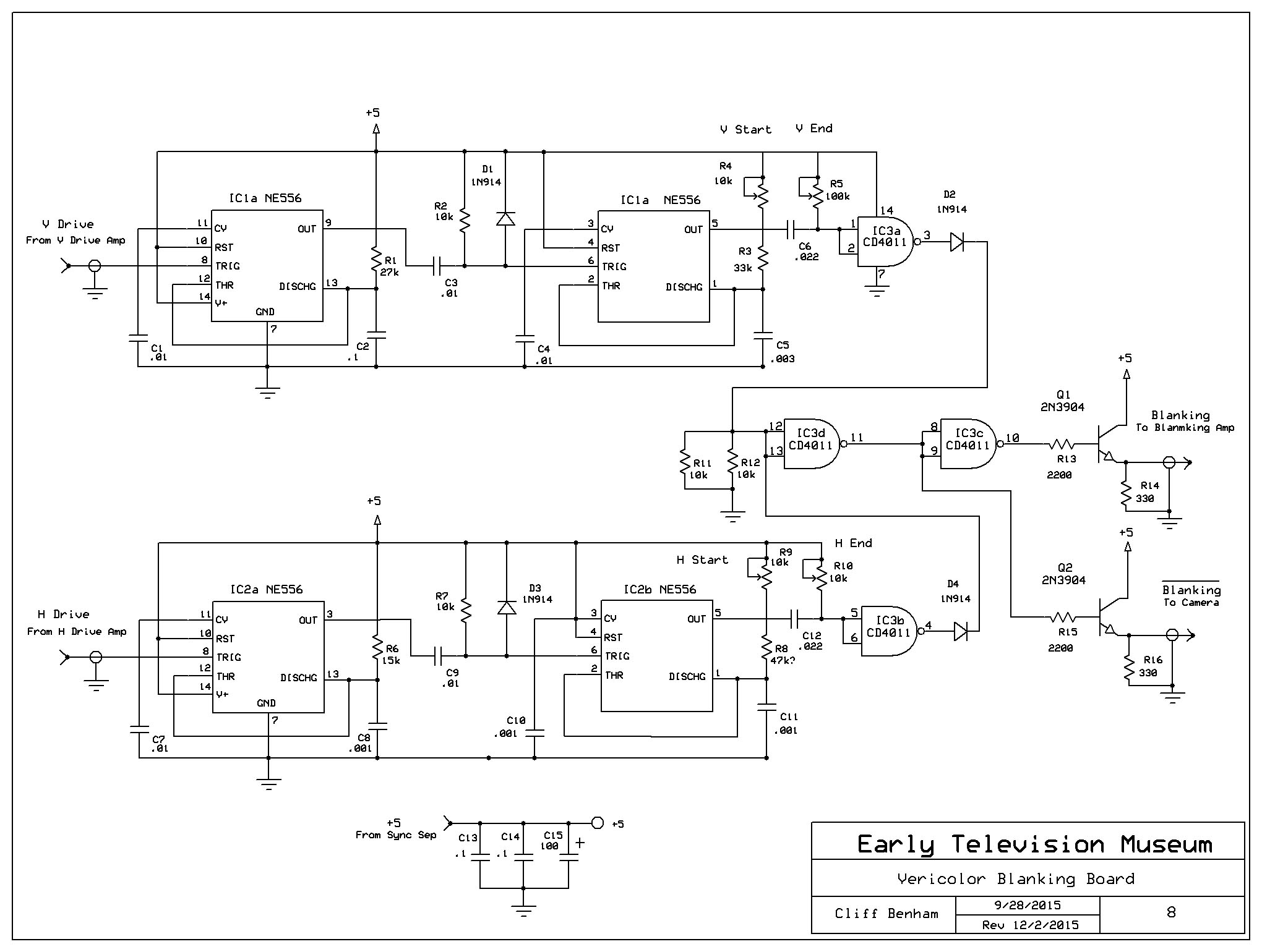
There are many problems to fix. First, the picture has no blanking. I will need to build a circuit to insert the blanking. Then, the picture has too much green. The original Vericolor CCU extracts the frames for each color and allows the video gain to be adjusted for each color. Cliff Benham is designing something that will do that. Other problems include poor focus (don't have a proper lens yet) and low contrast (video output is less than 1 volt). September 19, 2015 I built a crude blanking inserter, which helps the picture quality significantly. I also used a CFL for lighting, rather than the incandescent lamp I'd been using. The result is a much better picture
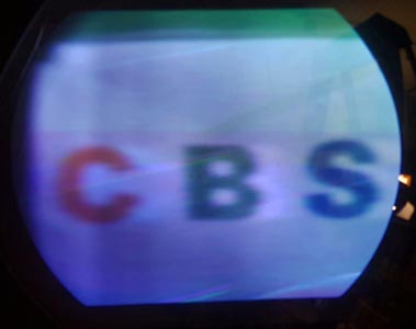
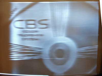
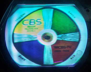
The picture has various types of garbage in it. It is noisy, and there is some sort of beat the wanders up the screen. When I disconnect the video preamp from the IO tube, the background is completely clean, and isn't noisy. That means that the garbage is coming from the IO tube. I will try additional filtering on the 1500 volt power supply to see if that is the source of the beat. I will also retry some of the IO tubes that produced an image to see if they are better. Cliff Benham suggested that I get a 6500 K CFL to get better color balance. September 20, 2015 The picture gets better. I got a 6500 K bulb, which improved the color balance. I determined that there was radiation from the 1500 V power supply, which I cured by wrapping shielding around the leads to the supply. Most of the remaining noise in the picture is because I need to crank up the targe and beam to get 1 v video (the Vericolor manual shows the camera preamp's video output at .3v). Cliff Benham is building a video amp to increase the .3 v to 1 v.
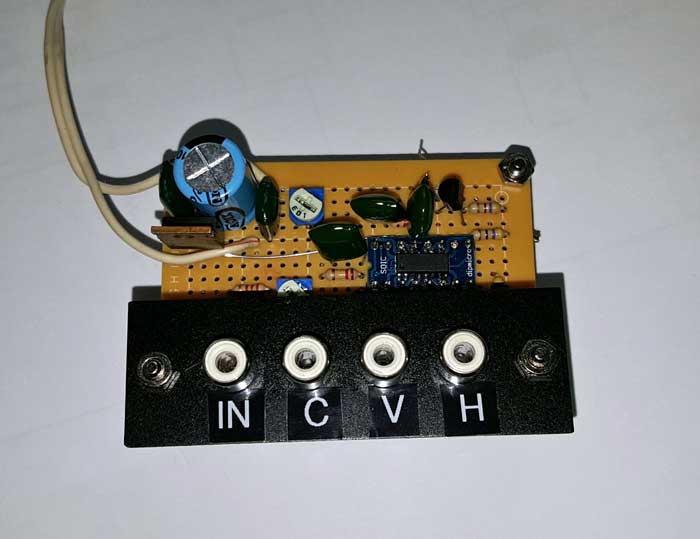
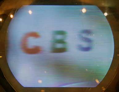
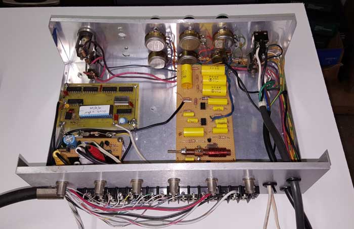
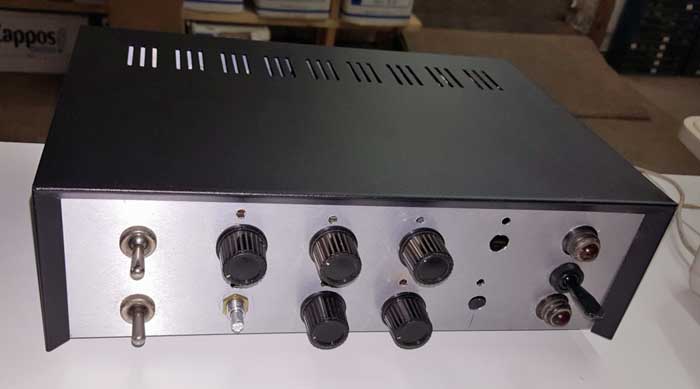
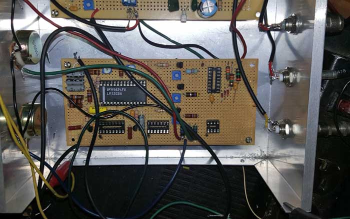
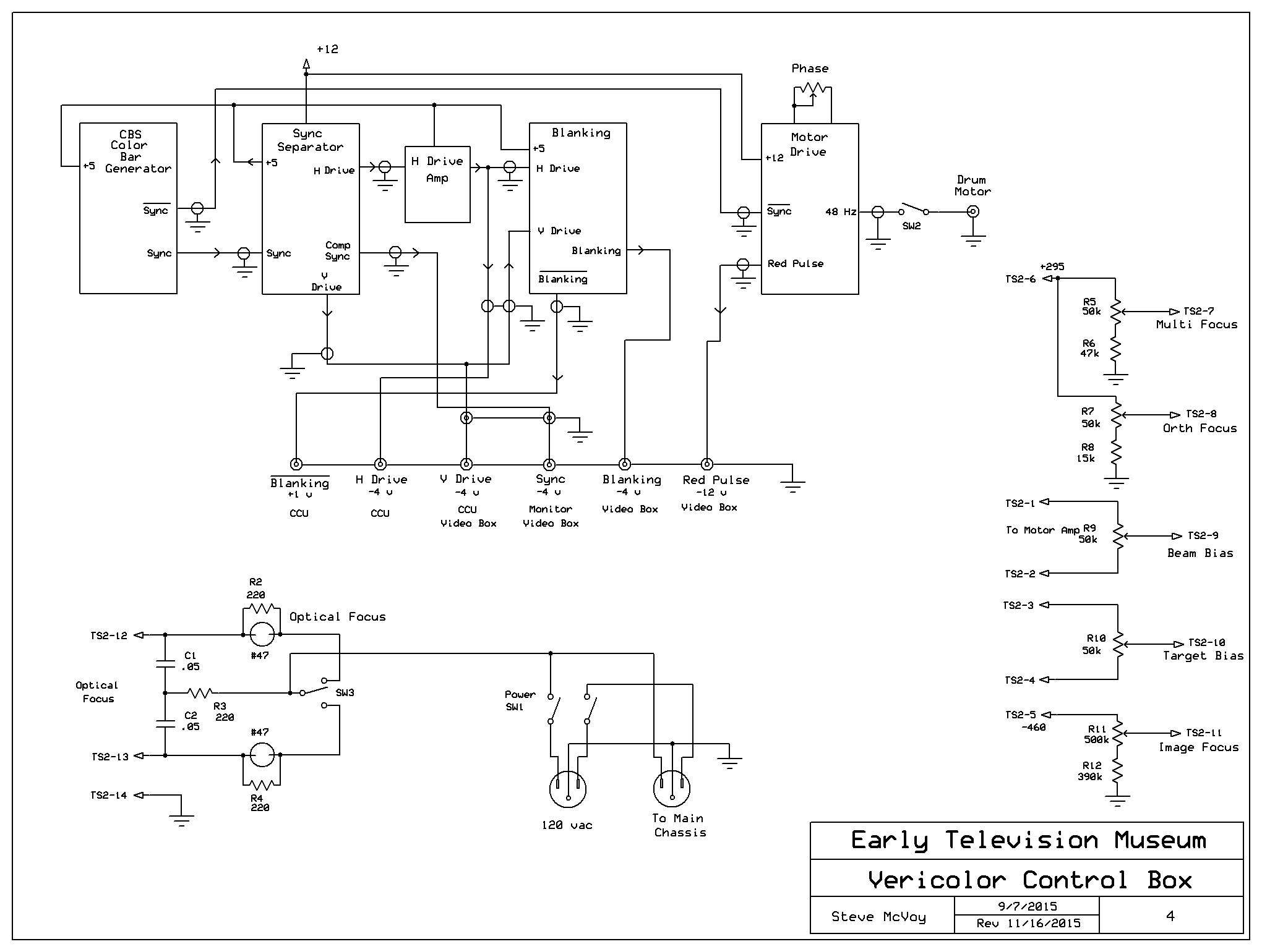
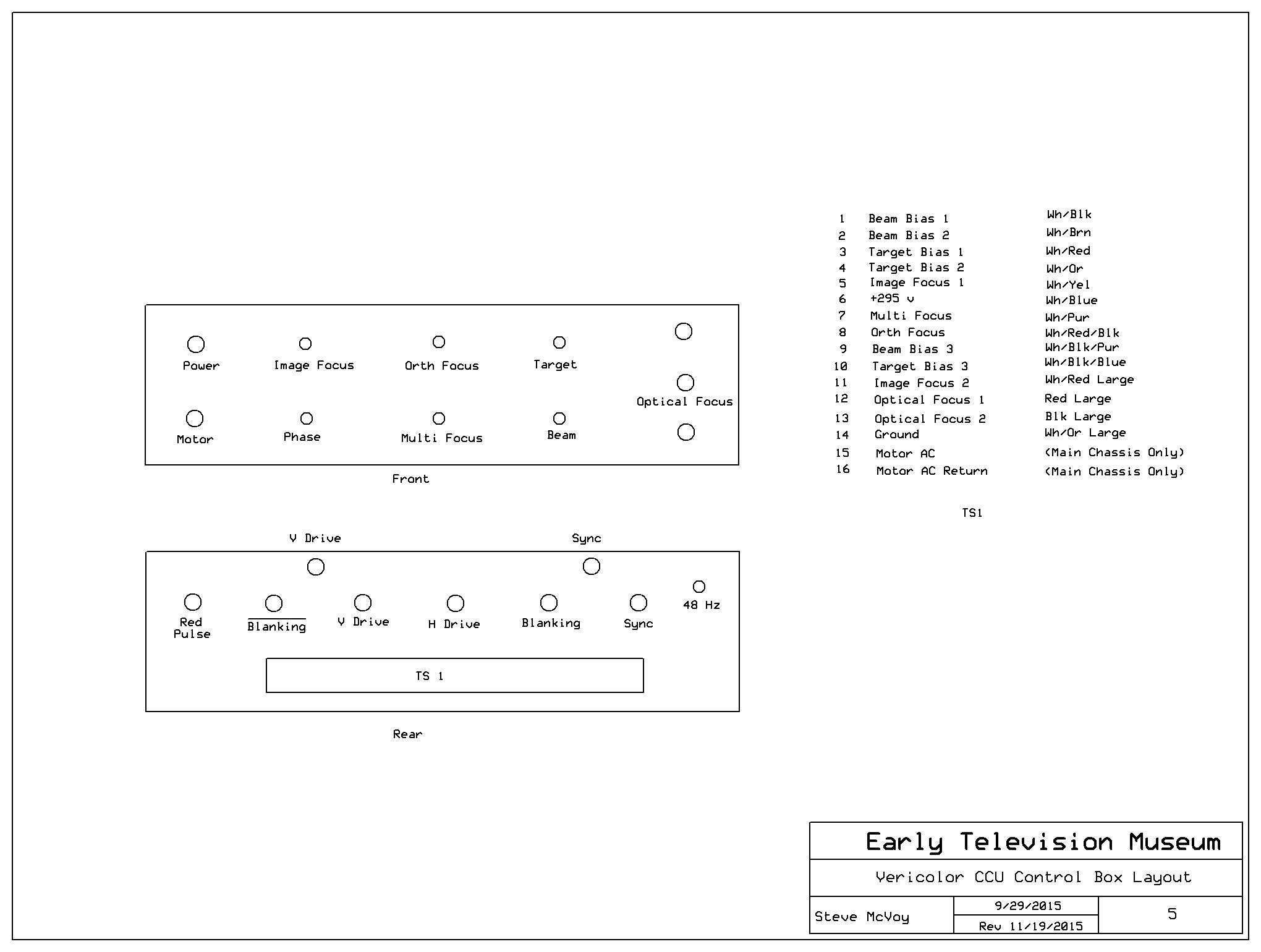
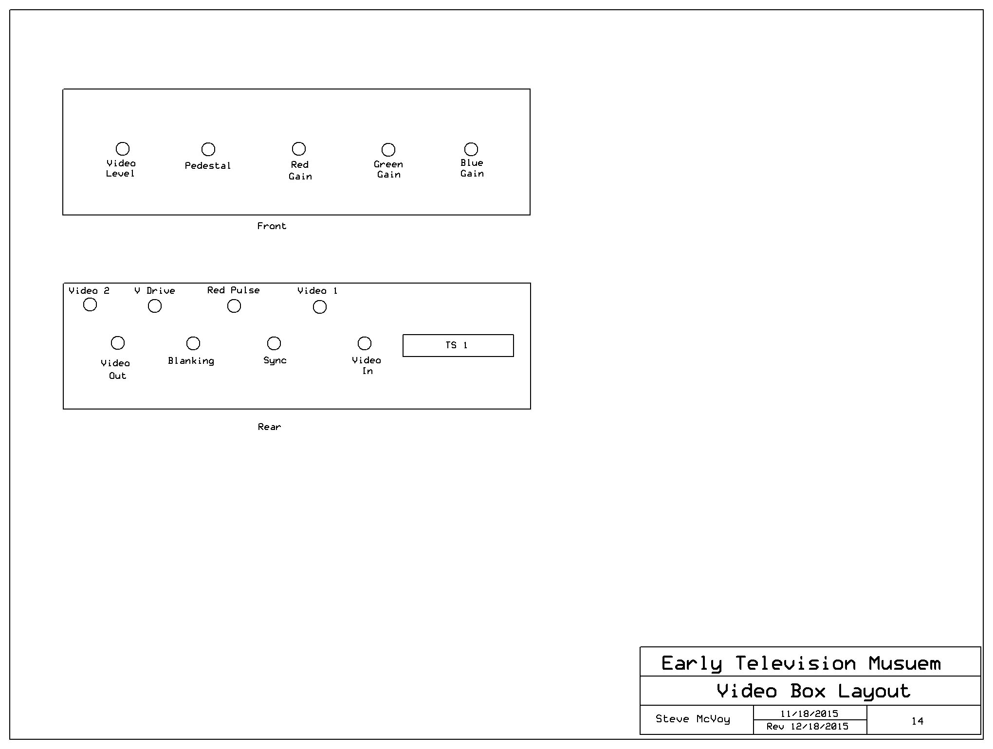
(The red spot at the bottom of the S is a reflection of a Sylania neon sign nearby. You can see another reflection of it above the C). September 22, 2015 While I am waiting for the remaining components, I started construction of the control box, which will be located on the top of the Gray monitor. It will contain the operator controls, the video/sync boards, and the motor drive boards. A 15 conductor cable will connect it to the existing chassis. September 24, 2015 Here is the control box, mostly completed. It is missing the video amp, which should be here tomorrow. I still need to work out a good way of inserting blanking and setting the pedestal.
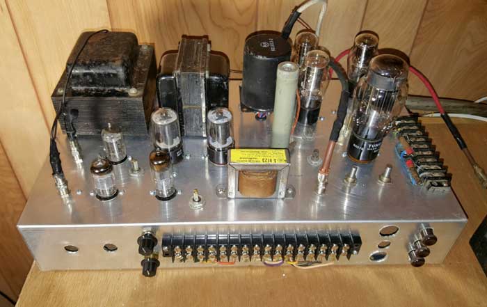
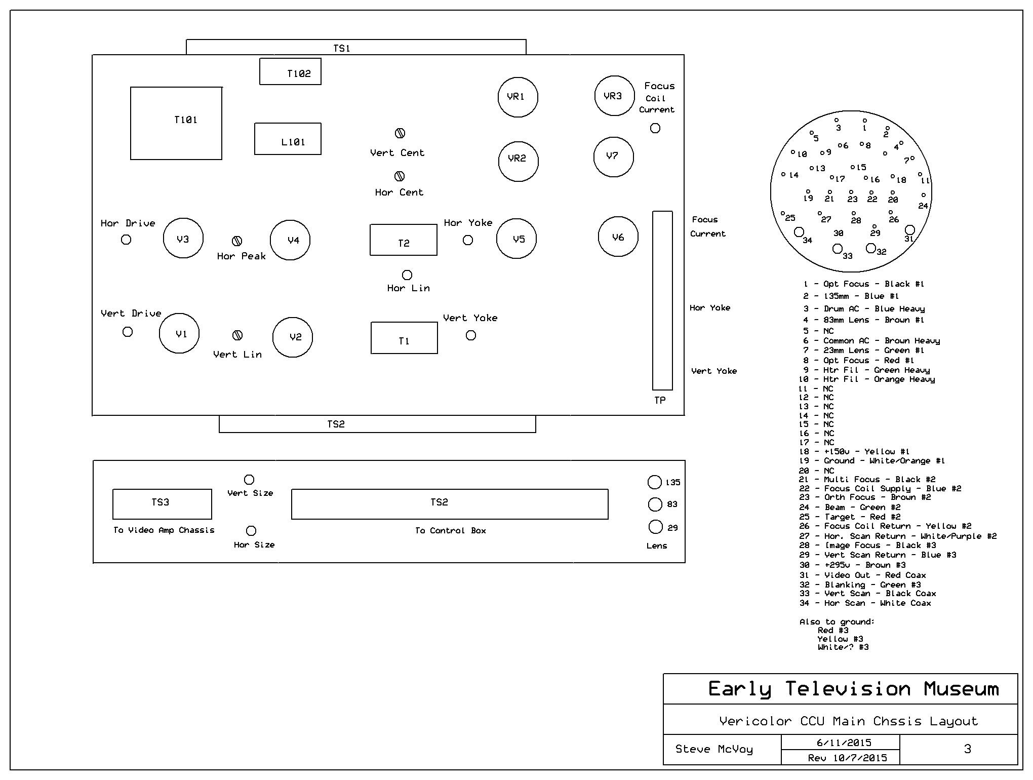
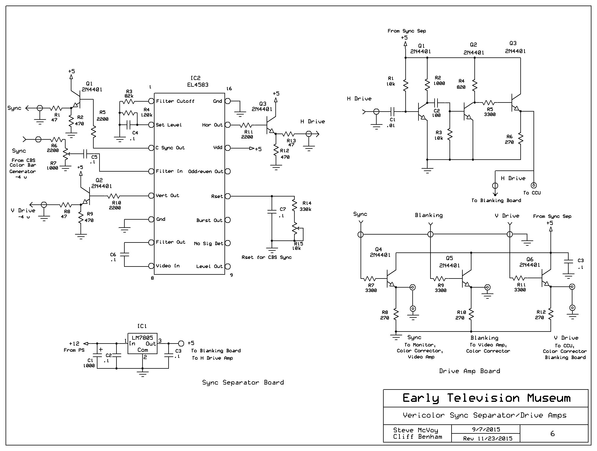
Here is the main chassis, with the controls removed and a new terminal strip to connect it to the control box: September 29, 2015 The control box is now finished. I had a lot of trouble getting the NE555 on the blanking board to trigger from the H drive signal, but I think it is working reliably now. I'll post schematics soon.
The motor drive board (finds red sync pulse and generate 48 Hz for the motor amp) in on the left. Top center is the video amp. Bottom center is the blanking board. Top right is the sync separator board, and bottom right is the CBS color bar generator. Front panel controls are power, motor power, 48 Hz phase, 5 IO controls, video gain, and optical focus. Next is to put it on top of the Gray monitor and see how good a picture I can get. October 3, 2015 Once everything was re-assembled, I was able to get a picture with good vertical resolution, but terrible horizontal resolution. My first idea was that there was a problem with the video preamplifier in the camera:
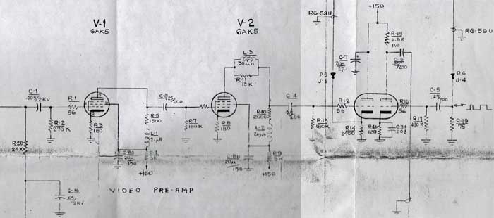
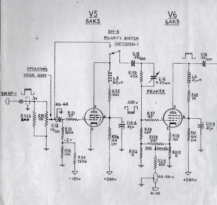
I checked the response of the amplifier, and found that it rolled off significantly below 1 kHz, but was flat to about 3 mHz. I replaced the three coupling capactiors, and improved the low end, but it is still down by about 6 dB at 30 Hz. I realized that this is part of the design - C1 is only .005, compared with .25 for the other two coupling capacitors. I think this is because C1 needs to be 2000 v rating because there is 1500 vdc on the IO output. A .25/2000v capacitor would have been too big to fit in the amp housing, so the engineers made a compromise. In any case, the high frequency response is fine, so the resolution problem isn't in the preamp. I then read the Vericolor manual, and discovered that the output of an IO is 80 times lower at high frequencies. The video amplifier in the CCU has a circuit that corrects for this:
R193 is bypassed by C16, which allows the high frequncies to reach the grid of V6, while attenuating the lower frequencies. I have decided to build the same circuit, but with a modification to insert blanking into the grid of V5. I also may have to add a cathode follower to get a low impedance output. This circuit will also allow me to add horizontal shading. After looking at the circuit I think that the video amplifier will put out only about .2 volts, so I will run it into the solid state amp that Cliff built. The video level control and blanking insertion will take place there. October 8, 2015 I made considerable progress with the camera. The video amp chassis is complete except for two peaking inductors, which I will wind today. When I first turned it on, here are the pictures I got:
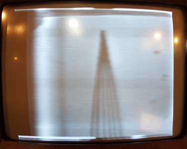
As you can see, the horizontal resolution is much improved. However, notice the wavy lines in the first picture. It looks like some sort of RF interference. I spent some time trying to track it down, and finally determined that it is created by having the target and beam too high on the IO. When they are turned down, the lines disappear. However, I don't have enough gain in the video amps to produce a picture with the proper contrast.
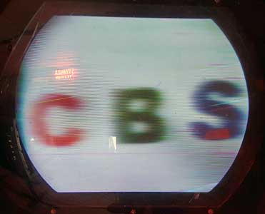
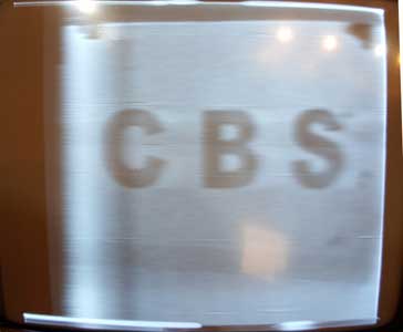
Here is a color picture. The picture looks sharper in real life. Notice the white ghost to the right of the letters. Something is not right in the video amplifiers, Next I will find a way to increase the gain of the video amps, wind the peaking inductors, and see what is going on with the ghost. October 9, 2015 I discovered the cause of the wiggly vertical lines:
Looking at the horizontal sweep waveform I discovered that it was not a linear sawtooth, but was somehow reset just outside the blanking interval. Somehow this caused ringing that was picked up by the IO tube. I experimented with changing component values in the sawtooth generator, and was able to eliminate the ringing. Today I'll try to find the cause of the reset. After experimenting with component values in the horizontal sawtooth generator circuit I was able to eliminate the wiggles, and the sweep waveform looks good going into the horizontal output tubes. However, there is still shading in the picture, indicating that the IO is not being swept linearly:
In the image on the right you can see how much better the sharpness is. Here is the first picture of color bars: I wound some inductors for the video amp, but, as you can see, there is still a white ghost (CBS letters). Also, there is still not enough video gain, and the horizontal blanking interval is too long (about 20% of the line). I will work on these problems next. Octoboer 12, 2015 Today I concentrated on fixing the blanking and checking the linearity of the picture. The H drive signal from the sync separator was not a very good square wave, and wouldn't reliably trigger the NE555 in the blanking generator. I built a two transistor amplifier to create good square pulses (top trace). This fixed the NE555, and I changed the time constants to create a blanking interval of about 5 microseconds (bottom trace).
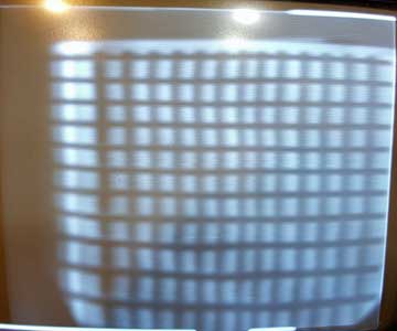
Next I made a crosshatch pattern to check linearity. The horizontal linearity is pretty good. On the far left there is another verical line but it is masked by some sort of shading which I still don't understand. At first I thought it was sweep distortion, but if that were happening the linearity wouldn't be good. I'll try another IO tube to see if that fixes the problem. The vertical linearity is off, but should be easy to fix with some experimentation with caps.
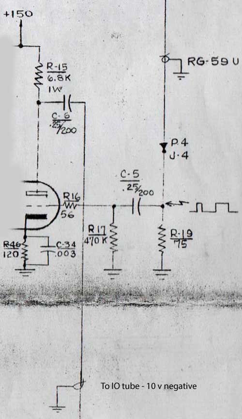
The final thing I did was look at the blanking going to the IO tube. Here is the circuit that produces it, with an imput from my blanking generator board of about 1 v positive:
However, the waveform is very rounded, indicating there is a problem somewhere. Top trace is the H drive signal.: October 16, 2015 After carefully checking all the components in the camera blanking amplifier I have determined that it is working as it was designed. I made adjustments in the H and V blanking periods to make them about what the CBS specs call for (.18 H and .1 V). Next I spent some time on linearity.
As you can see, it is now reasonably good. I had to change the resistor in series with the height control to get the vertical right. The horizontal was more messy. I ended up with a 40 mfd capacitor from F1 to ground (see Vericolor CCU Schematic P1) to get good horizontal linearity. This isn't right, since it impedes the operation of the damper. I'll work on his some more. However, I have significant shading issues. Notice the bright white vertical band at the left, followed by a dark band, then a less intense white band and another black band. Since the linearity is good, the problem isn't scanning, but something from the scanning signal getting into the video. You can also see in the picture that the IO focus is reasonably good (see the converging horizontal lines in the photo), but the horizontal resolution is poor (converging vertical lines). Also, the white following ghost is still there (to the right of the S in CBS). Still some work to do in the video amp. More experimentation with the horizontal sweep. First, I changed the input capacitor (C9) and resistor (R15) to make a differentiator, creating a negative going pulse at the beginning of the pulse, and therby starting the horizontal sweep at that point. Previously the sweep didn't start until the end of the drive pulse. This solved much of the shading problem. Later I'll work on improving the horizontal linearity. The vertical linearity could also be better.
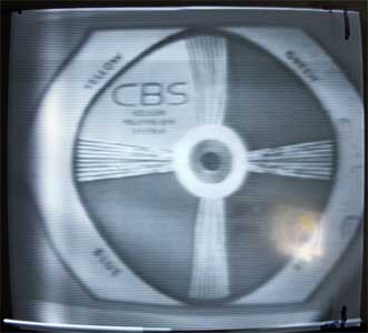
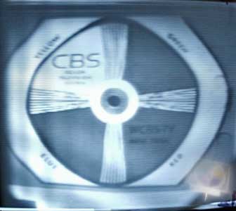
You can see from this picture that the IO focus is decent (vertical resolution), but the horizontal resolution is not too great. Here is a shot with the camera closer to the test pattern:
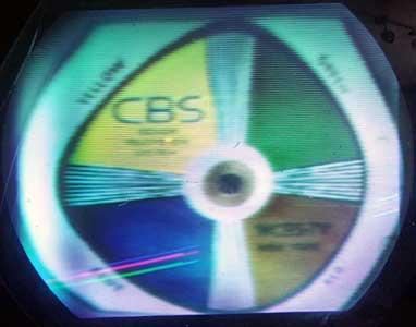
I adjusted the trimmer in the video amplifier chassis to create the best resolution (you can see the lines, but they lack contrast. The best adjustment of the trimmer also resulted in elimnation of the ghosting. I will need to explore further why the horizontal resolution isn't better. Here is the color picture. A great improvment.
Notice the three retrace lines in the bottom of the picture. They are because our blanking circuit is triggered by the leading edge of the vertical drive pulse, so there is no front porch. The Gray monitor vertical and horizontal linearity needs to be adjusted.
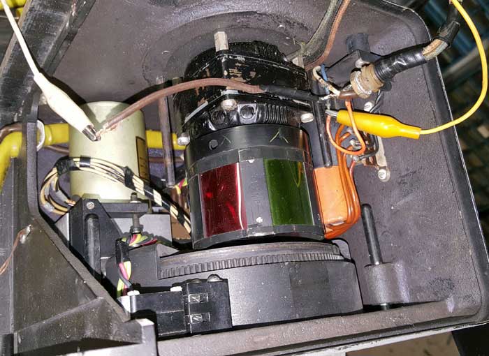
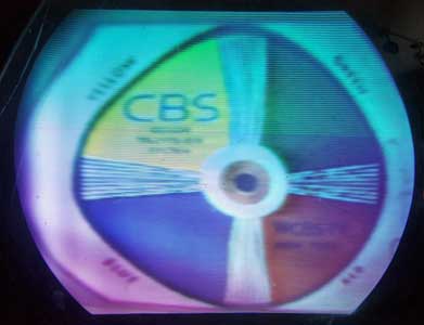
Cliff Benham suggested we use a 6500 K light source. Here is the picture - much better color balance. I cleaned and inspected the color drum today. The filters are in bad shape:
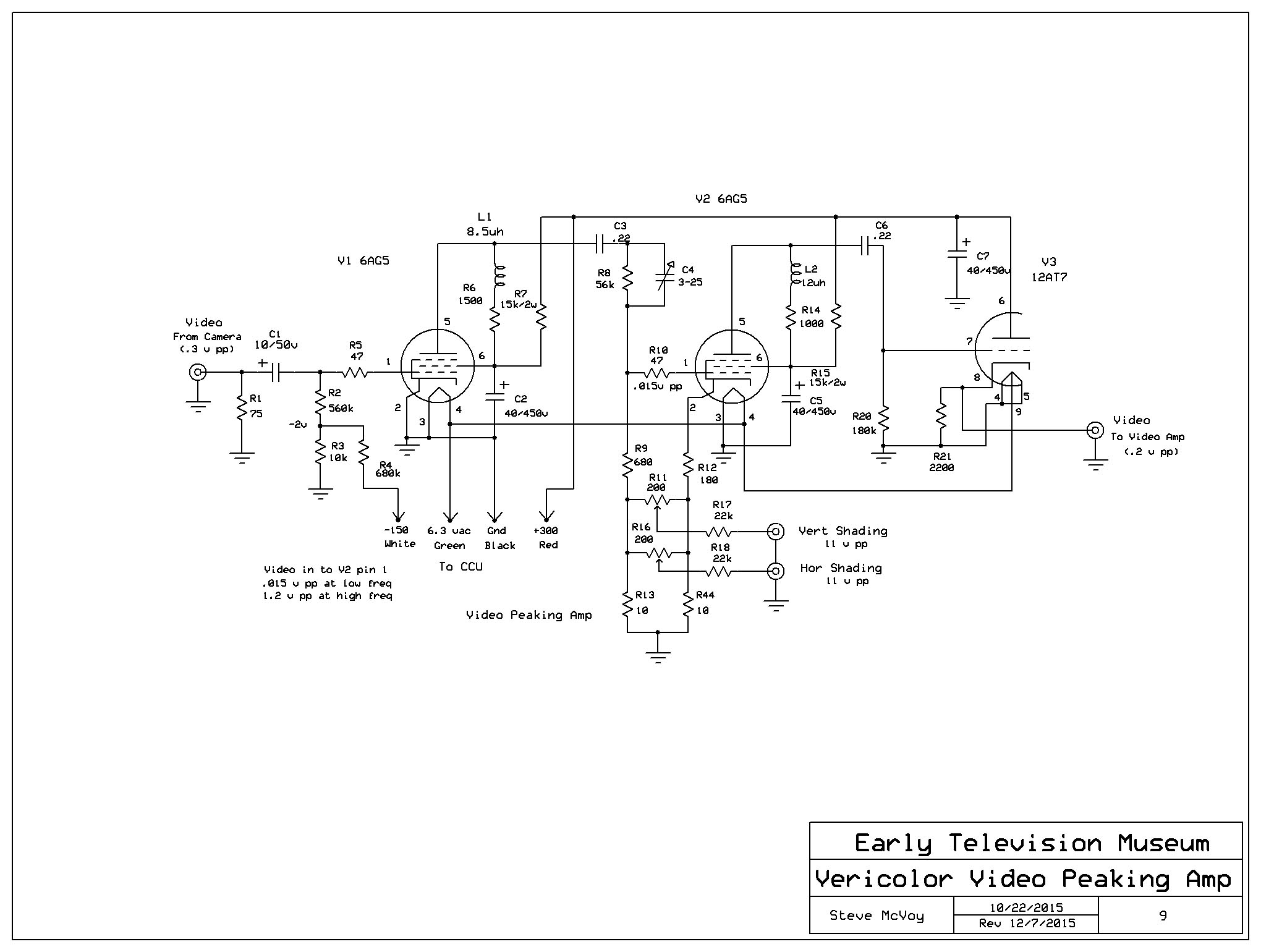
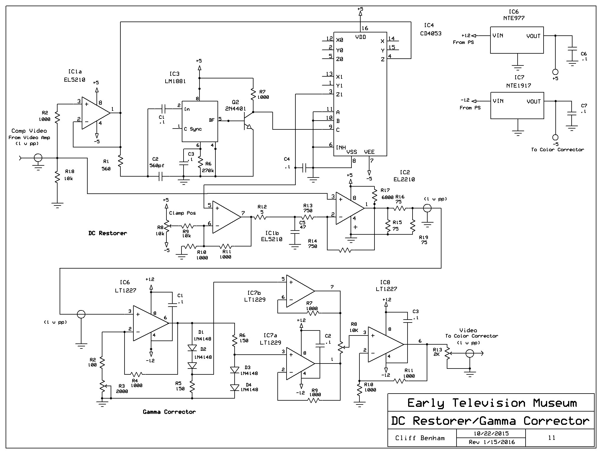
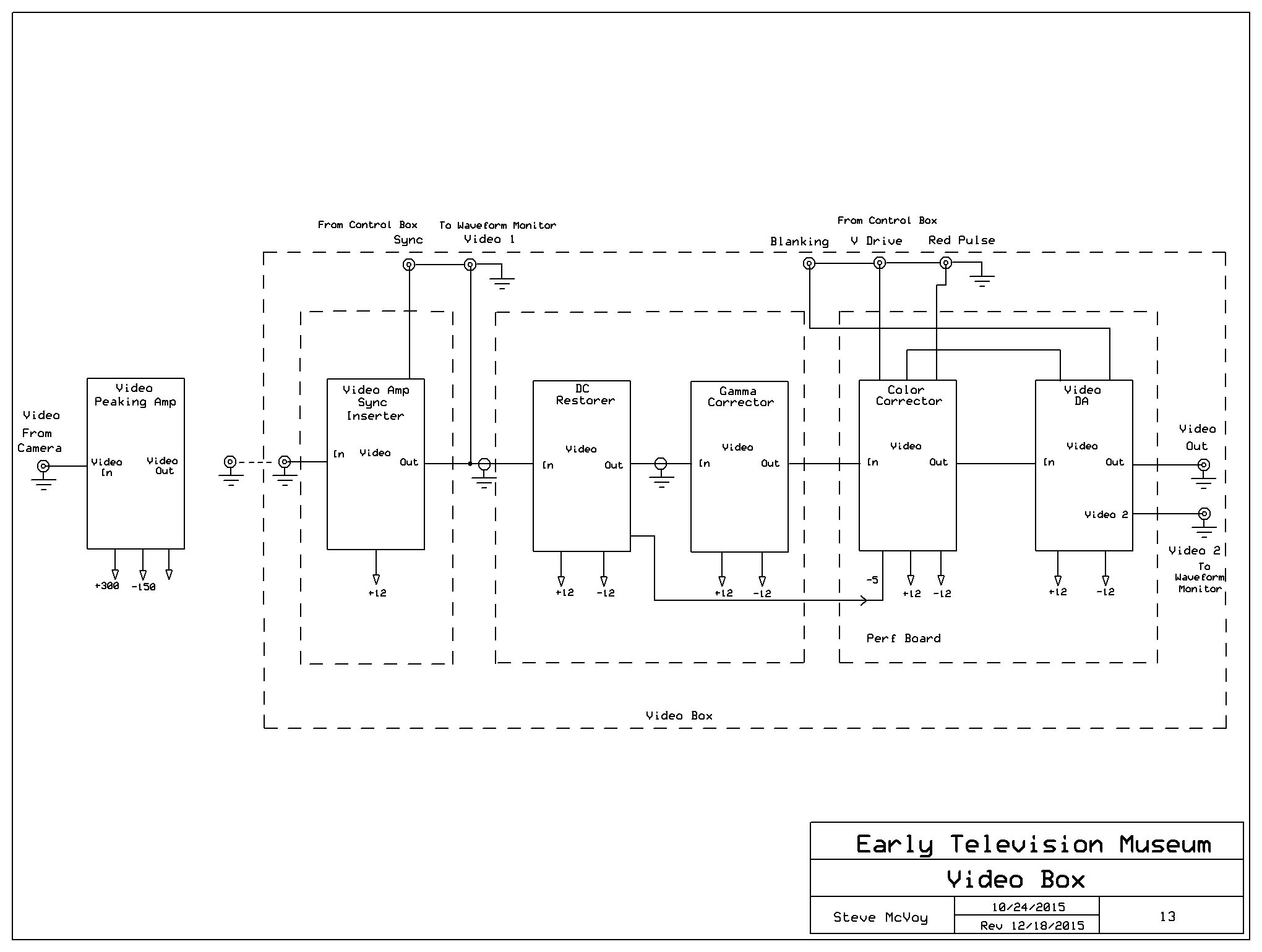
The next project is to build the color balance and gamma correction circuits. Cliff Benham supplied datasheets for the LM1203 RGB video amplifier chip and a Gamma correction circuit using LT1227 and LT1229 video op amps. I've ordered the chips. A switching circuit, to select R, G and B fields, will be designe by Cliff. October 23, 2015 After much discussion, Cliff and I have figured out the best way to implement the color correction. Video from the camera head (.3 v pp) will go to the tube type video peaking amplifier, which compensates for the high frequency rolloff of the IO tube. Output is about .2 v pp. This feeds a video amplifier built by Cliff.This amplifies the video to 1 v pp and inserts sync and blanking. Next is a DC restorer built by Cliff, which is needed to assure correct operation of the gamma correction circuit. This unit also removes the sync. Next will be a board I am making, which will have a gamma correction circuit., followed by switching circuitry to separate the three colors to provide for individual gain controls, and a video distribution amplifier. I received the proper peaking coils for the video peaking amplifier and installed them. This made no difference in the horizontal resolution. Next I will sweep the entire video section to see what its response is. October 24, 2015 Today I made some improvement in the linearity of the Gray monitor. Below are pictures from the camera on the B & W monitor and the Gray. The marks on the screen on the B & W monitor are the corners of an image from Darryl's standards converter. Notice that the camera image starts well to the right of the marks. This is because the sweep is messed up (see waveform below). I have concluded that this is due to the use of a horizontal output transformer from a TK-31 camera rather than the one that was originally used. The number of turns in the original transformer is noted on the schematic. I will contact Heyboer to see if that is enough information for them to make a replica. For now, the image below on the Gray is the best I can do. I've adjusted the width and centering of the monitor to match the image from the camera.
Next I worked on the horizontal resolution. I discovered that the camera preamp wasn't terminated. Adding a 75 ohm termination greatly improved the resolution (you can now see the vertical lines in the test pattern). The peaking amplifier now drives the solid state video amp directly, and there is an impedance mismatch. I'll add a cathode follower to the peaking amp. October 26, 2015 I experimented with the horizontal drive pulse into the CCU. Notice in the above picture of the B & W monitor that the sweep is offset to the right about 20% from where it should be. The above waveform shows that the sweep starts after the end of the H drive pulse. I built a circuit to shorten the pulse from 5 microseconds to about 1 microseconds, and this shifted the picture to the proper place.
You can see great improvement in the horizontal resolution. I added a cathode follower to the video peaking amplifier. For some reason this also cleaned up the color purity. I still have some work to do on the horizontal linearity of the Gray monitor. I will now focus on the color corrector. First will be to modify the video amp to add sync insertion. Sync is needed for the DC restorer that follows (the DC restorer removes the sync, too). October 28, 2015 I was able to improve the linearity of the Gray monitor:
I got sidetracked by an oscillation in the video. It occurs only when the gain control is turned up to about the right place and when the cable to the monitors is connected. I'm not sure what is going on, but I plan on moving the solid state video amp out of the CCU control box and into a new box for the video processing stuff. Maybe that will fix it. October 30, 2015 I finished moving the video amplifier to a new box, which will also contain the DC restorer, gamma corrector, and color corrector. The oscillation problem disappeared. Here are screen shots. Notice that most of the poor horizontal linearity is in the Gray monitor. Also notice how good the horizontal resolution is getting.
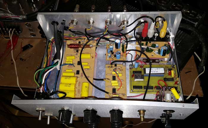
Here is the box for the video processing equipment. On the left is the video amplifier, which was previously in the CCU control box. Next to it is the DC restorer, built by Cliff Benham. I'll add the gamma corrector on the front of this board. On the right will go the color corrector board. The control in the left is video gain. Next to it will be the pedestal control. The other three pots are the R, G, and B level controls. November 3, 2015 Today I built a video amplifier using an op amp. It works great, with a gain of over 5. Its output can easily be adjusted for 1 v pp video to feed the DC restorer. The DC restorer works well also, stripping the sync off as it should. Here is the new video amp in the cabinet:
I discovered I had miswired the gamma corrector. I assumed the ICs were for a single supply, but, in fact, they require a + and - supply. I will rewire it tomorrow. When the replacement IC arrives I'll be ready to test it. Here are some photos of the test setup:
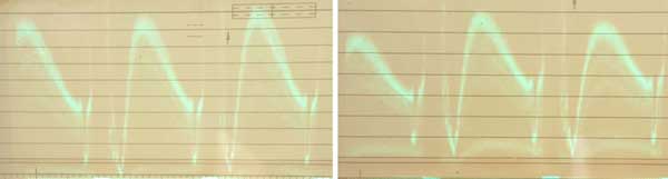
The camera control box is on top of the Gray monitor. The CCU sweep chassis is on its side on the cabinet, and the video processing box is behind the soldering iron. November 4, 2015 Here is the picture with the new video amp and the DC restorer. Also, I made some changes to the horizontal sweep section to improve linearity.
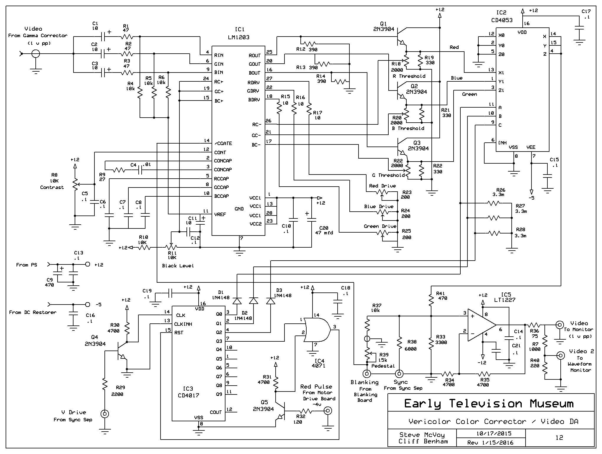
November 14, 2015 In the last few days I have rewired the Gamma Corrrector for + and - 5 volt supplies. I've also added a pot on its output to adjust to 1 v pp. The Gamma Corrector appears to work like it should - Cliff Benham sent me a logarithmic grey scale chart, and I've crudely made the adustments to get the right waveform. I'll get back to that later. Here is the Color Corrector board:
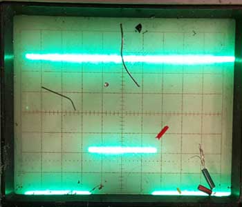
I've installed only the 3 channel video amp chip, and have tested the video output. Two of the channels appear to work properly, the third has a problem. Tomorrow I'll troublshoot it. Next step will be to install the switching chip and manually address it to make sure it works. Finally, I'll install the counter chips. November 16. 2015 As it always goes with troubleshooting solid state stuff, I've chased a couple of bad op amps, probably the result of my shorting their outputs. The 1203 is working on all three channels now, but I have a ringing in the video. Power supply bypassing has reduced it greatly, but it is still visible in the blanking inverval on a scope. Another problem is that the 47 ohm resistors in the transistors that interface between the 1201 and the CD4053 get very hot. I think this is a design problem - I'll replace them with a larger value. I've put that aside for now to work on the switching. I installed the CD4053 analog switch, and it works as it should. Applying a positive voltage on pins 9,, 10 and 11 swiches color channels. Finally, I installed BNC connectors on the back of the cabinet for the V Drive and Red Pulse from the Camera Control Box. Next I need to install another BNC connector on the Camera Control Box for the Red Pulse output. Tomorrow I'll finish that and get the counter circuits to work on the Color Corrector. November 18, 2015 I cured the ringing by putting a 47 mfd capacitor directly from pin 1 of the 1201 to the ground buss. I replaced the 47 ohm resistors with 330 ohm. One of the transistors (Q1) had been trashed by the high current (the result of th e 47 ohm emitter resitors). Replacing the transistor made all three channels work properly,. I installed two additional BNC connectors on the back of the CCU Control Box and connected the red pulse and v drive signals to the video box. The switching circuit didn't work, and I was able to determine that the transistor (Q4) that feeds the v drive signal to the 4017 wasn't working. I'll diagnose that next. Gettng close to the end! I found the problem with the switching logic. First, there was a mistake in the schematic, which I corrected. Also, the inductor in the red pulse detector can be set to two different places. Both work fine for the motor, but one produces a second pulse, which messes up the switching logic. Here are the waveforms now (top trace is the red pulse, sweep width is 3 fields) Notice the wire scraps on the scope face. It is on the floor directly below where I'm working:
It would be nice to report that the three gain controls work fine, and that I can change the color balance of the image on the Gray monitor. No such luck. The gain controls don't work right, and the image on the monitor is either all red, all blue or all green, depending on the phase. However, when this is fixed, we will be almost finished with this project. All that will be left is the video DA, which should be easy. November 19, 2015 I found the problem with the analog switch - a couple of wiring mistakes. It now works perfectly.Here are waveforms:
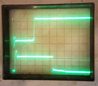
If you look at the Gray monitor screen, the image it displays is the color that is on. The final stage is building and testing the video DA. The ICs for this just arrived, and tomorrow I'll make the circuit. I will also experiment with inserting blanking and sync at the input of this amplifier. November 23. 2015 The waveform below shows how degraded the red filter in the drum is. The camera is aimed at a white piece of paper. Notice how low the video level is in the red (first) field compared to the blue and green.
I've had a series of pulses in the vertical blanking interval of the video signal that I haven't been able to find the source of. They come directly from the IO tube, despite the proper blanking signal being applied to the tube. Sometimes they are 3-4 times the amplitude of the video. These pulses mess up the DC restorer and Gamma Corrector, so I designed a circuit to eliminate them. It consists of a CD4053 analog switch that switches the video to ground during blanking and allows the video to pass at other times. That eliminates anything, including the undesired pulses, that are inside the blanking inverval. I have added this circuit just after the video amp. I have also added emitter followers to alll the signal outputs from the Control Box (sync, blanking, H drive, V drive, red pulse). This cleans up the waveforms and provides a low impedance source for the cables and circuitry that is connected. Cliff has finished building a proper blanking generator. The one I built starts the blanking interval for both V and H at the start of the drive pulses. His positions the blanking pulses so that they start before the dirve pulses, as the CBS specs call for. This should eliminate the retrace lines we see in the picture. I finished the Blanking Stripper. It eliminates retrace lines. In addition, it makes the picture extend to the top of the screen. Not quite sure it does this. I also got the Gamma Corrector to work properly, and did a preliminary adjustment of it. Here are pictures with all the ciruits connected, and with red and green gain at maximum and blue at about 50%. I didn't pay attention to focus in these pictures, so the resolution doesn't look great:
Today I'll change the light source from 6500K to 3500K to see if that improves the red. November 24, 2015 Best color yet December 3, 2015 I've spent the last two days cleaning things up. I had a couple of loose connections to track down. I also fixed the 60 Hz hum in the video. A 1/2 inch wide braided strap to connect the Video Peaking Amp to the Video Box fixed it. I also added a series resistor and filter capacitor in the +300 v line to the Video Peaking Amp to stop a motorboating problem. Finally, I put the two control boxes on top of the Gray monitor so that it is easy to adjust things while watching the monitors.
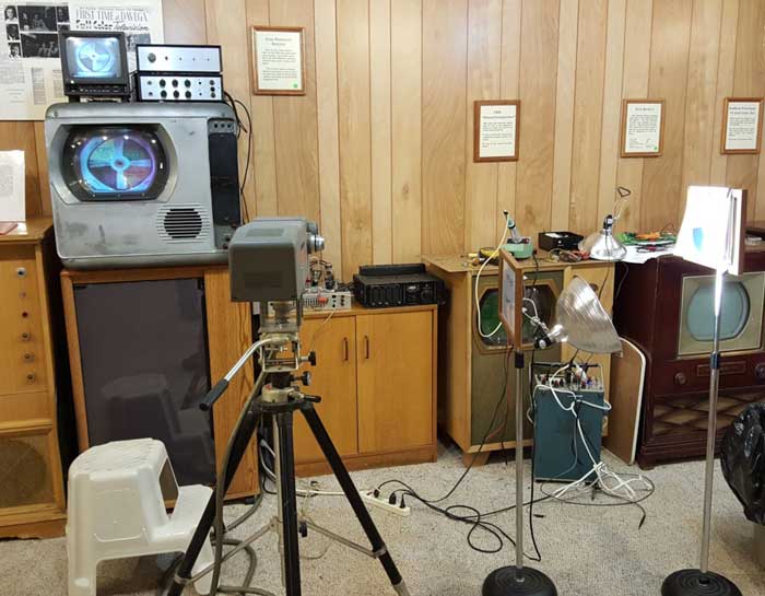
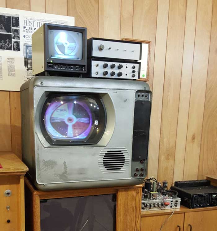
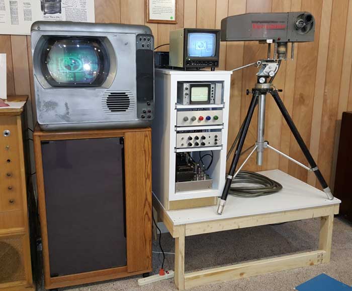
The overal setup
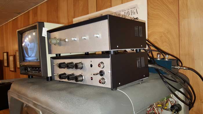
The two monitors, with the two control boxes
The control boxes, with the Video Peaking Amp in the background
The main chassis, and the temporary motor drive audio amp I've made great progress on color accuracy, mainly because of the color gain controls. Replacing the filters on the drum (especially the red one) will help even more.
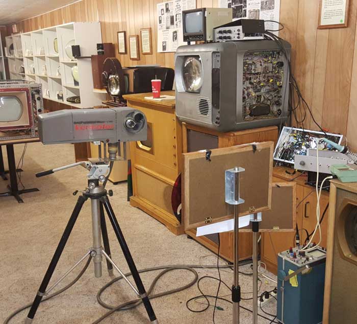
I bought a couple of miniature solid state oscilloscopes that I though would work as waveform monitors. Unfortunately it doesn't look like they will work. I need to find something that would be suitable, since one is needed to set up the camera. When the camera is turned on, it can come up with one of 3 phases. To make sure the fields are right, a piece of red paper is placed in front of the camera. Using a scope synced by the red field pulse and displaying 3 fields, one of the fields will have a higher video level. That's the red field. By turning off the drum motor momentarily you can get the red field to be first after the red field pulse. Then the color gain controls will work properly. Cliff Benham has finished the blanking generator board. When it arrives I'll replace the one I built. His design should properly position the picture, both vertically and horizontally, and eliminate the remaining high intensity pulse in the VBI. December 16, 2015 This week I've been making a platform and cabinet to display the camera. I built a 4x 3 foot platform, 18 inches high to support the tripod, camera, and a 15 inch wide kitchen base cabinet. I installed three shelves on rollouts for the waveform monitor, video box and CCU control box. The main (deflection) chassis is on the bottom. For on top of the cabinet is the B & W picture monitor. For now the audio amp that drives the drum motor is on the top.
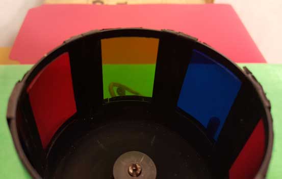
The front and sides of the platform will be covered with white paneling. The camera will aim toward the curtain across the aisle. There will be a background of some sort, and lights suspended from the ceiling. The idea is that a person can stand there and see himself on the Gray monitor in CBS color. Since the video output has composite sync, it can be fed to a modulator to be viewed by our other CBS receivers. For now, this project is finished. There are still a few bugs to work out, but the camera is working well. December 27, 2015 One more issue to be dealt with. It is difficult to get good reds from the camera. They appear too yellow. I made some measurments of the light transmission characteristics of the camera drum filters to get some ideas. Here is what I did. I turned off the motor and manually put each color filter in front of the IO tube. Then I aimed the camera at different colors (color source) and measured the video output signal. Here are the results:
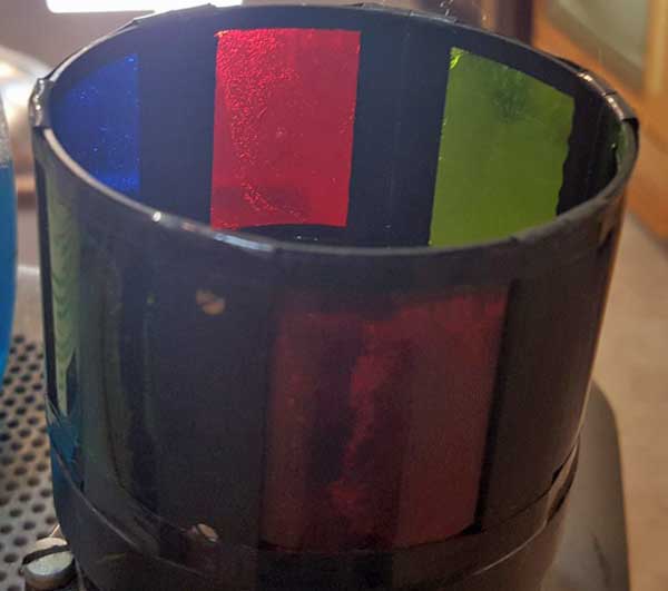
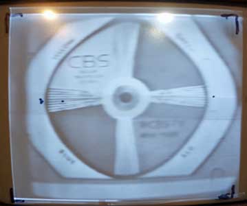
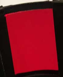
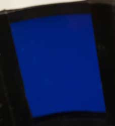
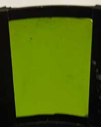
The red and blue filters are working about as they should, passing significanlty more red and blue that other colors. However, the green filter passes as much red as green, thus explaining the yellowing appearance of the red source. Here are photos taken through the three filters with a white backgroud:
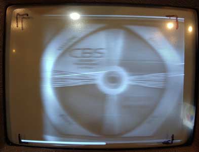
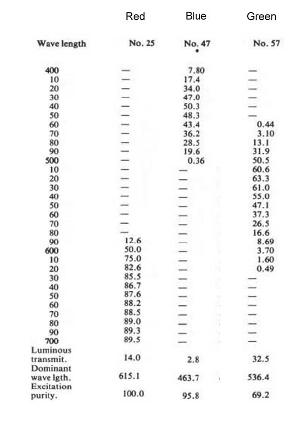
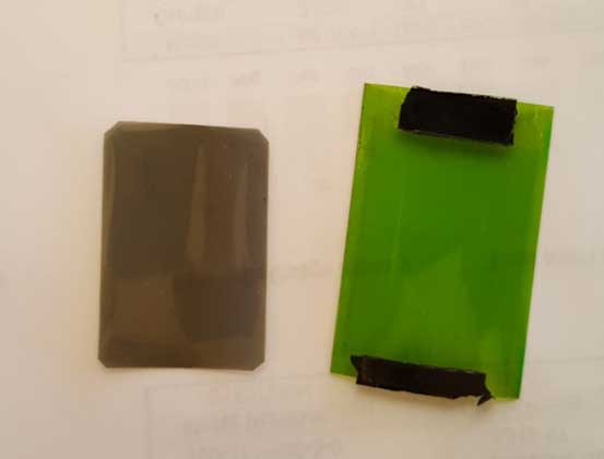
As you can see, the red and blue filters have vivid colors, while the green filter is washed out. It may have faded over the years. I will insert a piece of green filter material I have left over from a color wheel project in place of the drum and measure the light transmission characteristics of it. Another possibility is IR contamination of the image. I will try an IR filter to test that theory. However, here are the specs of the Kodak Wratten filters that were probably used in the camera. Notice that none other than the red filter pass any light in that spectdrum: January 6, 2016 Here is a picture taken through the green filter onto a red and green subject. If the filter was blocking red and passing green, like it should, the red portion should appear almost black, but it is actually red. The green filter is the reason for poor red response.
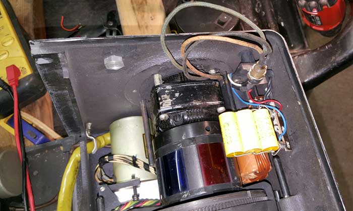
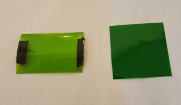
A neutral density filter is below the green filter January 9, 2015 The filters arrived from Cliff today. Here is a #58 Wratten, compared to the original filter. Notice how much darker it is:
I replaced the green segments with the #58 filter and re-installed the two neutral density filters. Now the picture has lots of red. The IR blocking filter had no effect, except to attenuate all colors. The problem was clearly that the original green filters had faded.
Tomorrow I'll do a more careful job of color balancing. January 11, 2016 Today I measured the video output from the the colors with different lighting. Here is the result:
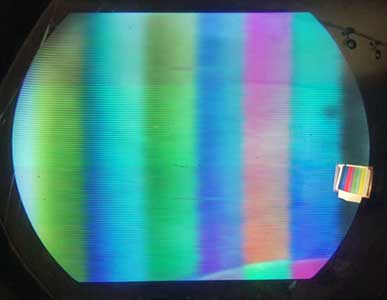
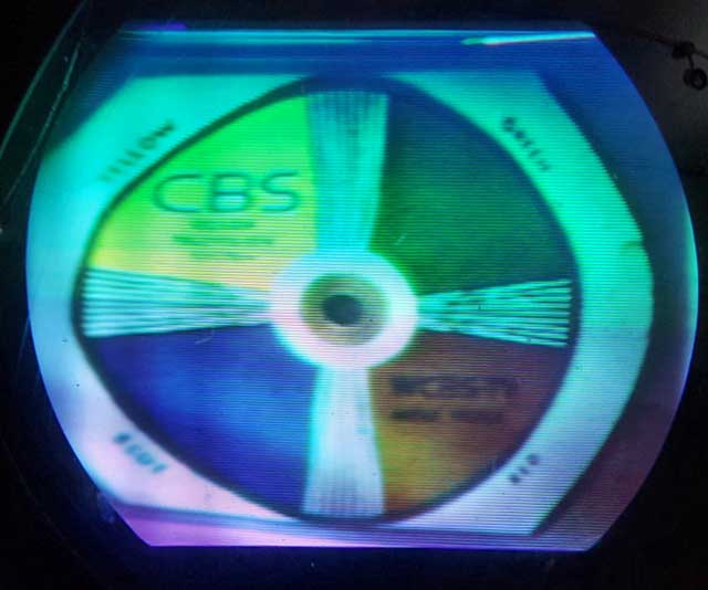
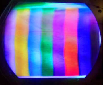
The fields are red, blue and green, and the subject is a white piece of poster board. I made no attempt to get the light evenly distributed over the subject, or to carefully adjust the IO. As you can see, the 2700K light source produces video outputs that are fairly even, with red down some and green up some. The 3500K light source produces more blue output, with red down significantly and green down some. January 12, 2016 Today I tested the color response using a color bar chart. The results were excellent:
The horizontal banding is an artifact of the digital camera. Look at the top third of the picture to see what it actually looks like. Notice that the bottom of the image is a good clean white, indicating that the color balance is about right. This is with 2700K lighting and the color gain controls all at minimum (equal levels).
| ||||||||||||||||||||||||||||||||||||||||||||||||||||||||||||||||||||||
