|
Television Experimenters.com
Basic Hardware
|
NIPKOW DISK Patented in 1884, this was the first practical scanning device able to break up camera images in to a series of impulses. It was also used to re-assemble those same impulses into the original image. The apertures are typically small holes, but lenses can also used. Accurately made disks can provide good image quality although the images are generally small. Disk diameter generally ranges from 8 to 24 inches. A system using Nipkow disks is the ideal construction project for the experimenter just starting out.
|
|
LENS DISKS An early improvement over the Nipkow disk was the lens disk. It was much more efficient in that the lens could pass many times more light compared to the the small apertures of the original Nipkow. There were as many lenses as there were lines in the picture and the focal center of each lens was at the at the same point as the aperture in the standard Nipkow. As it rotated, each lens caused a line to be scanned below the previous one.
|
|
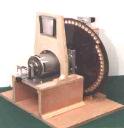
MIRROR DRUM Arrived on the scene about five years after the Nipkow. Originally it used mirrors, one for each image line. Optically, it much more efficient than the Nipkow. Later on, variations of the drum type of construction were also used with apertures, lenses and prisms. Drums are a good construction project for the advanced experimenter.
|
|
MIRROR SCREW Patented in 1928 by an American, it is the best, but least known of the mechanical scanners. It consists of a stack of thin mirrors, one for each image line arranged like a spiral staircase. The image is as large as the mirror stack and is viewed on the long mirror edges as it rotates. The optical efficiency is very high, therefore bright images are obtainable. Probably the best mechanical scanner used in sets for the home. Ideal for the advanced experimenter.
|
|
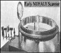
MIHALY-TRAUB SCANNER The Mihaly-Traub scanner was basically mirror drum turned inside out. It consists of a ring of stationary mirrors (one for each line), all facing inward. Each mirror has tilt adjustments, just as those on a mirror drum. In the center of the ring, there is a motor driven mirror, silvered on both sides. It rotates at half the picture rate. A beam of light, modulated with the picture signal is directed under the mirror ring to the lower part of the rotating mirror.
|
|
CATHODE RAY TUBE The modern cathode ray tube (CRT) is the result of numerous television pioneers efforts over a period of many years. By 1935, CRT images were beginning to be as good or better than those produced mechanically. The CRT also proved to be much more versatile and best able to be adapted to higher definition systems. CRTs are well suited for all image formats, including those normally used with mechanical systems. Many types of CRTs are readily available and well suited for use by the advanced experimenter.
|
The hardware family listed above is of course just a small portion of
what is actually necessary to successfully produce images. But these
items are the key elements that can make a system into a television
system. |

All rights reserved. |